Advertisements
Advertisements
Question
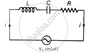
For an LCR circuit driven at frequency ω, the equation reads
`L (di)/(dt) + Ri + q/C = v_i = v_m` sin ωt
- Multiply the equation by i and simplify where possible.
- Interpret each term physically.
- Cast the equation in the form of a conservation of energy statement.
- Integrate the equation over one cycle to find that the phase difference between v and i must be acute.
Advertisements
Solution
Consider L-C-R series circuit with AC supply
V = Vm sin ωt
Applying voltage Kirchhoff's law over the circuit
∴ VL + VC + VR = Vm sin ωt
L = `(di)/(dt) + Ri + q/c` = Vi = Vm sin ωt
Multiply the above equation by i on both the sides.
L = `(di)/(dt) + Ri + q/c` = Vi = Vm sin ωt
Multiply the above equation by `1/2` on both sides
`1/2 Li (di)/(dt) + i q/(2C) + (i^2R)/2 = 1/2` Vmi sin ωt `(∵ i = (dq)/(dt))`
`(d(1/2 Li^2))/(dt) + 1/(2C) (dq^2)/(dt) + (i^2R)/2 = 1/2` Vmi sin ωt .....(I)
(i) `(d(1/2 li^2))/(dt)` Represents the rate of change of potential energy in inductance L.
(ii) `d/(dt) q^2/(2C)` represents energy stored in dt time in the capacitor.
(iii) i2R represents joules heating loss.
(iv) `1/2 V_m i` sin ωt is the rate at which driving force pours in energy. It goes into ohmic loss and increase of stored energy in capacitor and inductor.
Vi = rate at which driving force pours in energy. It goes into (i) ohmic loss and (ii) increase of stored energy.
Hence equation (ii) is in the form of conservation of energy statement. Integrating both sides of equation. (ii) with respect to time over one full cycle (0 → T) we may write
`int_0^T d/(dt) (1/2 Li^2 + q^2/(2C)) dt + int_0^T Ri^2 dt = int_0^T Vi dt`
⇒ 0 + (+ ve) = `int_0^T Vi dt`
⇒ `int_0^T Vi dt > 0` if phase difference between V and i is a constant and acute angle.
APPEARS IN
RELATED QUESTIONS
Define 'quality factor' of resonance in a series LCR circuit. What is its SI unit?
A series LCR circuit is connected across an a.c. source of variable angular frequency 'ω'. Plot a graph showing variation of current 'i' as a function of 'ω' for two resistances R1 and R2 (R1 > R2).
Answer the following questions using this graph :
(a) In which case is the resonance sharper and why?
(b) In which case in the power dissipation more and why?
A voltage V = V0 sin ωt is applied to a series LCR circuit. Derive the expression for the average power dissipated over a cycle. Under what condition (i) no power is dissipated even though the current flows through the circuit, (ii) maximum power is dissipated in the circuit?
(i) Find the value of the phase difference between the current and the voltage in the series LCR circuit shown below. Which one leads in phase : current or voltage ?
(ii) Without making any other change, find the value of the additional capacitor C1, to be connected in parallel with the capacitor C, in order to make the power factor of the circuit unity.

In a series LCR circuit, obtain the condition under which watt-less current flows in the circuit ?
Show that in an a.c. circuit containing a pure inductor, the voltage is ahead of current by π/2 in phase ?
A series LCR circuit is connected to a source having voltage v = vm sin ωt. Derive the expression for the instantaneous current I and its phase relationship to the applied voltage.
Obtain the condition for resonance to occur. Define ‘power factor’. State the conditions under which it is (i) maximum and (ii) minimum.
Find the value of t/τ for which the current in an LR circuit builds up to (a) 90%, (b) 99% and (c) 99.9% of the steady-state value.
An inductor of inductance 2.00 H is joined in series with a resistor of resistance 200 Ω and a battery of emf 2.00 V. At t = 10 ms, find (a) the current in the circuit, (b) the power delivered by the battery, (c) the power dissipated in heating the resistor and (d) the rate at which energy is being stored in magnetic field.
Consider the circuit shown in figure. (a) Find the current through the battery a long time after the switch S is closed. (b) Suppose the switch is again opened at t = 0. What is the time constant of the discharging circuit? (c) Find the current through the inductor after one time constant.

Answer the following question.
Draw the diagram of a device that is used to decrease high ac voltage into a low ac voltage and state its working principle. Write four sources of energy loss in this device.
Keeping the source frequency equal to the resonating frequency of the series LCR circuit, if the three elements, L, C and R are arranged in parallel, show that the total current in the parallel LCR circuit is minimum at this frequency. Obtain the current rms value in each branch of the circuit for the elements and source specified for this frequency.
For a series LCR-circuit, the power loss at resonance is ______.
The resonant frequency of a RF oscillator is 1 MHz and its bandwidth is 10 kHz. The quality factor will be :
Which of the following components of an LCR circuit, with a.c. supply, dissipates energy?
A series LCR circuit containing 5.0 H inductor, 80 µF capacitor and 40 Ω resistor is connected to 230 V variable frequency ac source. The angular frequencies of the source at which power transferred to the circuit is half the power at the resonant angular frequency are likely to be ______.
A series RL circuit with R = 10 Ω and L = `(100/pi)` mH is connected to an ac source of voltage V = 141 sin (100 πt), where V is in volts and t is in seconds. Calculate
- the impedance of the circuit
- phase angle, and
- the voltage drop across the inductor.
Which of the following statements about a series LCR circuit connected to an ac source is correct?
Draw the phasor diagram for a series LRC circuit connected to an AC source.
