Advertisements
Advertisements
Question
Consider the LCR circuit shown in figure. Find the net current i and the phase of i. Show that i = v/Z`. Find the impedance Z for this circuit.

Advertisements
Solution
In the circuit given above consists of a capacitor (C) and an inductor (L) connected in series and the combination is connected in parallel with a resistance R. Due to this combination, there is an oscillation of electromagnetic energy.
Potential across R = Potential of source
P.D. across R =Vm sin ωt
i2R = Vm sin ωt
`I_2 = (V_m sin ωt)/R` ......(I)
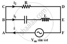
q1 is charge on the capacitor at any time t, then for series combination of C, L applying Kirchhoff's voltage law in loop ABEFA.
VC + VL = Vm sin ωt
`q_1/C + L (di_1)/(dt)` = Vm sin ωt
`q_1/C + L (d^2q_1)/(dt^2)` = Vm sin ωt ......(II)
Let q1 = qm sin(ωt + ϕ) .......(III)
`i_1 = (dq_1)/(dt)` = qm ω cos(ωt + ϕ) .......(IV)
`(d^2q_1)/(dt^2)` = qm ω2 sin(ωt + ϕ) ......(V)
Substitute the values of equations (III) and (V) in equation (II)
`(q_m sin(ωt + ϕ))/C - Lq_m ω^2 sin(ωt + ϕ)` = Vm sin ωt
`q_m sin(ωt + ϕ) [1/C - Lω^2]` = Vm sin ωt
At ϕ = 0,
`q_m sin(ωt + ϕ) [1/C - Lω^2]` = Vm sin ωt
`q_m [1/C - Lω^2] sin ωt` = Vm sin ωt
`q_m [1/C - Lω^2]` = Vm
`q_m = V_m/(ω[1/(Cω - Lω)]` ......(VI)
Applying Kirchhoff's junction rule as junction B, i = i1 + i1 using relation I, IV
i = `(V_m sin ωt)/R + q_m ω cos(ωt + ϕ)`
Now using relation VI for qm and at ϕ = 0
i = `[(V_m sin ωt)/R + (V_m ω cos ωt)/(ω[1/(ωC) - ωL])]`
i = `V_m/R sin ωt + V_m/((1/(ωC) - ωl)) cos ωt`
Let A = `V_m/r -= C cos ϕ` ......(VII)
B = `V_m/(1/(ωC) - ωL) = C cos ϕ` ......(VIII)
i = C cos ϕ sin ωt + C sin ϕ. cos ωt
= C [cos ϕ sin ωt + sin ϕ cos ωt]
i = C sin(ωt + ϕ)
Squaring and adding (VII), (VIII)
A2 + B2 = C2 cos2ϕ + C2 sin2ϕ
= C2[cos2ϕ + sin2ϕ]
A2 + B2 = C2
or C = `sqrt(A^2 + B^2)`
ϕ = `tan^-1 B/A = tan^-1 ((V_m)/(1/(ωC) - ωL))/((V_m)/R)`
∴ `tan phi = R/((1/(ωC) - ωL))`
∵ C2 + A2 = B2 = `(V_m^2)/R^2 + (V_m^2)/((1/(ωC) - ωL)^2)`
C = `[(V_m^2)/R^2 + (V_m^2)/((1/(ωC) - ωL)^2)]^(1/2)`
∵ i = `[(V_m^2)/R^2 + (V_m^2)/((1/(ωC) - ωL)^2)]_2 sin(ωt + ϕ)`
I = `V_m [1/R^2 + 1/((1/(ωC) - ωL)^2)]^(1/2) sin(ωt + ϕ)` ......(IX)
And ϕ = `tan^-1 R/((1/(ωC) - ωL))`
∵ I = `V/R` or i = `V/Z`
For ac i = `V/Z sin(ωt + ϕ)` .......(X)
Comparing (IX) and (X)
So, `1/Z = [1/R^2 + 1/((1/(ωC) - ωL)^2)]^(1/2)`
This is the impedance Z for the circuit.
APPEARS IN
RELATED QUESTIONS
A series LCR circuit is connected across an a.c. source of variable angular frequency 'ω'. Plot a graph showing variation of current 'i' as a function of 'ω' for two resistances R1 and R2 (R1 > R2).
Answer the following questions using this graph :
(a) In which case is the resonance sharper and why?
(b) In which case in the power dissipation more and why?
A voltage V = V0 sin ωt is applied to a series LCR circuit. Derive the expression for the average power dissipated over a cycle. Under what condition (i) no power is dissipated even though the current flows through the circuit, (ii) maximum power is dissipated in the circuit?
(i) Find the value of the phase difference between the current and the voltage in the series LCR circuit shown below. Which one leads in phase : current or voltage ?
(ii) Without making any other change, find the value of the additional capacitor C1, to be connected in parallel with the capacitor C, in order to make the power factor of the circuit unity.

Derive an expression for the average power consumed in a series LCR circuit connected to a.c. source in which the phase difference between the voltage and the current in the circuit is Φ.
An LR circuit contains an inductor of 500 mH, a resistor of 25.0 Ω and an emf of 5.00 V in series. Find the potential difference across the resistor at t = (a) 20.0 ms, (b) 100 ms and (c) 1.00 s.
An LR circuit with emf ε is connected at t = 0. (a) Find the charge Q which flows through the battery during 0 to t. (b) Calculate the work done by the battery during this period. (c) Find the heat developed during this period. (d) Find the magnetic field energy stored in the circuit at time t. (e) Verify that the results in the three parts above are consistent with energy conservation.
(i) An a.c. source of emf ε = 200 sin omegat is connected to a resistor of 50 Ω . calculate :
(1) Average current (`"I"_("avg")`)
(2) Root mean square (rms) value of emf
(ii) State any two characteristics of resonance in an LCR series circuit.
What will be the potential difference in the circuit when direct current is passed through the circuit?
Derive an expression for the average power dissipated in a series LCR circuit.
Keeping the source frequency equal to the resonating frequency of the series LCR circuit, if the three elements, L, C and R are arranged in parallel, show that the total current in the parallel LCR circuit is minimum at this frequency. Obtain the current rms value in each branch of the circuit for the elements and source specified for this frequency.
For a series LCR-circuit, the power loss at resonance is ______.
In an L.C.R. series a.c. circuit, the current ______.
To reduce the resonant frequency in an LCR series circuit with a generator ______.
In series LCR circuit, the plot of Imax vs ω is shown in figure. Find the bandwidth and mark in the figure.

A series LCR circuit driven by 300 V at a frequency of 50 Hz contains a resistance R = 3 kΩ, an inductor of inductive reactance XL = 250 πΩ, and an unknown capacitor. The value of capacitance to maximize the average power should be ______.
Three students, X, Y and Z performed an experiment for studying the variation of ac with frequency in a series LCR circuit and obtained the graphs as shown below. They all used
- an AC source of the same emf and
- inductance of the same value.

- Who used minimum resistance?
- In which case will the quality Q factor be maximum?
- What did the students conclude about the nature of impedance at resonant frequency (f0)?
- An ideal capacitor is connected across 220 V, 50 Hz, and 220 V, 100 Hz supplies. Find the ratio of current flowing through it in the two cases.
To reduce the resonant frequency in an L-C-R series circuit with a generator ______.
Which of the following combinations should be selected for better tuning of an L-C-R circuit used for communication?
When a capacitor is connected in series LR circuit, the alternating current flowing in the circuit ______
