Advertisements
Advertisements
प्रश्न
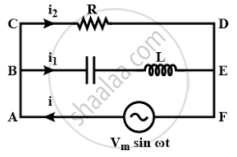
Consider the LCR circuit shown in figure. Find the net current i and the phase of i. Show that i = v/Z`. Find the impedance Z for this circuit.

Advertisements
उत्तर
In the circuit given above consists of a capacitor (C) and an inductor (L) connected in series and the combination is connected in parallel with a resistance R. Due to this combination, there is an oscillation of electromagnetic energy.
Potential across R = Potential of source
P.D. across R =Vm sin ωt
i2R = Vm sin ωt
`I_2 = (V_m sin ωt)/R` ......(I)
q1 is charge on the capacitor at any time t, then for series combination of C, L applying Kirchhoff's voltage law in loop ABEFA.
VC + VL = Vm sin ωt
`q_1/C + L (di_1)/(dt)` = Vm sin ωt
`q_1/C + L (d^2q_1)/(dt^2)` = Vm sin ωt ......(II)
Let q1 = qm sin(ωt + ϕ) .......(III)
`i_1 = (dq_1)/(dt)` = qm ω cos(ωt + ϕ) .......(IV)
`(d^2q_1)/(dt^2)` = qm ω2 sin(ωt + ϕ) ......(V)
Substitute the values of equations (III) and (V) in equation (II)
`(q_m sin(ωt + ϕ))/C - Lq_m ω^2 sin(ωt + ϕ)` = Vm sin ωt
`q_m sin(ωt + ϕ) [1/C - Lω^2]` = Vm sin ωt
At ϕ = 0,
`q_m sin(ωt + ϕ) [1/C - Lω^2]` = Vm sin ωt
`q_m [1/C - Lω^2] sin ωt` = Vm sin ωt
`q_m [1/C - Lω^2]` = Vm
`q_m = V_m/(ω[1/(Cω - Lω)]` ......(VI)
Applying Kirchhoff's junction rule as junction B, i = i1 + i1 using relation I, IV
i = `(V_m sin ωt)/R + q_m ω cos(ωt + ϕ)`
Now using relation VI for qm and at ϕ = 0
i = `[(V_m sin ωt)/R + (V_m ω cos ωt)/(ω[1/(ωC) - ωL])]`
i = `V_m/R sin ωt + V_m/((1/(ωC) - ωl)) cos ωt`
Let A = `V_m/r -= C cos ϕ` ......(VII)
B = `V_m/(1/(ωC) - ωL) = C cos ϕ` ......(VIII)
i = C cos ϕ sin ωt + C sin ϕ. cos ωt
= C [cos ϕ sin ωt + sin ϕ cos ωt]
i = C sin(ωt + ϕ)
Squaring and adding (VII), (VIII)
A2 + B2 = C2 cos2ϕ + C2 sin2ϕ
= C2[cos2ϕ + sin2ϕ]
A2 + B2 = C2
or C = `sqrt(A^2 + B^2)`
ϕ = `tan^-1 B/A = tan^-1 ((V_m)/(1/(ωC) - ωL))/((V_m)/R)`
∴ `tan phi = R/((1/(ωC) - ωL))`
∵ C2 + A2 = B2 = `(V_m^2)/R^2 + (V_m^2)/((1/(ωC) - ωL)^2)`
C = `[(V_m^2)/R^2 + (V_m^2)/((1/(ωC) - ωL)^2)]^(1/2)`
∵ i = `[(V_m^2)/R^2 + (V_m^2)/((1/(ωC) - ωL)^2)]_2 sin(ωt + ϕ)`
I = `V_m [1/R^2 + 1/((1/(ωC) - ωL)^2)]^(1/2) sin(ωt + ϕ)` ......(IX)
And ϕ = `tan^-1 R/((1/(ωC) - ωL))`
∵ I = `V/R` or i = `V/Z`
For ac i = `V/Z sin(ωt + ϕ)` .......(X)
Comparing (IX) and (X)
So, `1/Z = [1/R^2 + 1/((1/(ωC) - ωL)^2)]^(1/2)`
This is the impedance Z for the circuit.
APPEARS IN
संबंधित प्रश्न
In a series LCR circuit, obtain the condition under which watt-less current flows in the circuit ?
A series LCR circuit is connected to an ac source. Using the phasor diagram, derive the expression for the impedance of the circuit. Plot a graph to show the variation of current with frequency of the source, explaining the nature of its variation.
Derive an expression for the average power consumed in a series LCR circuit connected to a.c. source in which the phase difference between the voltage and the current in the circuit is Φ.
An LR circuit having a time constant of 50 ms is connected with an ideal battery of emf ε. find the time elapsed before (a) the current reaches half its maximum value, (b) the power dissipated in heat reaches half its maximum value and (c) the magnetic field energy stored in the circuit reaches half its maximum value.
An inductor of inductance 2.00 H is joined in series with a resistor of resistance 200 Ω and a battery of emf 2.00 V. At t = 10 ms, find (a) the current in the circuit, (b) the power delivered by the battery, (c) the power dissipated in heating the resistor and (d) the rate at which energy is being stored in magnetic field.
Two coils A and B have inductances 1.0 H and 2.0 H respectively. The resistance of each coil is 10 Ω. Each coil is connected to an ideal battery of emf 2.0 V at t = 0. Let iA and iBbe the currents in the two circuit at time t. Find the ratio iA / iB at (a) t = 100 ms, (b) t = 200 ms and (c) t = 1 s.
An ac circuit as shown in the figure has an inductor of inductance L and a resistor or resistance R connected in series. Using the phasor diagram, explain why the voltage in the circuit will lead the current in phase.
Using the phasor diagram, derive the expression for the current flowing in an ideal inductor connected to an a.c. source of voltage, v= vo sin ωt. Hence plot graphs showing the variation of (i) applied voltage and (ii) the current as a function of ωt.
At resonance frequency the impedance in series LCR circuit is ______.
The resonant frequency of a RF oscillator is 1 MHz and its bandwidth is 10 kHz. The quality factor will be :
Which of the following components of an LCR circuit, with a.c. supply, dissipates energy?
A series LCR circuit driven by 300 V at a frequency of 50 Hz contains a resistance R = 3 kΩ, an inductor of inductive reactance XL = 250 πΩ, and an unknown capacitor. The value of capacitance to maximize the average power should be ______.
Which of the following statements about a series LCR circuit connected to an ac source is correct?
When an alternating voltage of 220V is applied across device X, a current of 0.25A flows which lags behind the applied voltage in phase by π/2 radian. If the same voltage is applied across another device Y, the same current flows but now it is in phase with the applied voltage.
- Name the devices X and Y.
- Calculate the current flowing in the circuit when the same voltage is applied across the series combination of X and Y.
Draw a labelled graph showing variation of impedance (Z) of a series LCR circuit Vs frequency (f) of the ac supply. Mark the resonant frequency as f0·
In a series LCR circuit, the inductance L is 10 mH, capacitance C is 1 µF and resistance R is 100Ω. The frequency at which resonance occurs is ______.
A 20Ω resistance, 10 mH inductance coil and 15µF capacitor are joined in series. When a suitable frequency alternating current source is joined to this combination, the circuit resonates. If the resistance is made \[\frac {1}{3}\] rd, the resonant frequency ______.
To an ac power supply of 220 V at 50 Hz, a resistor of 20 Ω, a capacitor of reactance 25 Ω and an inductor of reactance 45 Ω are connected in series. The corresponding current in the circuit and the phase angle between the current and the voltage is respectively:
