Advertisements
Advertisements
प्रश्न
The current in a discharging LR circuit without the battery drops from 2.0 A to 1.0 A in 0.10 s. (a) Find the time constant of the circuit. (b) If the inductance of the circuit 4.0 H, what is its resistance?
Advertisements
उत्तर
The current in the discharging LR circuit after t seconds is given by
i = i0 e−t/τ
Here,
i0 = Steady state current = 2 A
Now, let the time constant be τ.
In time t = 0.10 s, the current drops to 1 A.
\[i = i_0 \left( 1 - e^{- t/\tau} \right)\]
\[ \Rightarrow 1 = 2\left( 1 - e^{- t/\tau} \right)\]
\[ \Rightarrow \frac{1}{2} = 1 - e^{- t/\tau} \]
\[ \Rightarrow e^{- t/\tau} = 1 - \frac{1}{2}\]
\[ \Rightarrow e^{- t/\tau} = \frac{1}{2}\]
\[ \Rightarrow \ln\left( e^{- t/\tau} \right) = \ln\left( \frac{1}{2} \right) = \]
\[ \Rightarrow - \frac{0 . 1}{\tau} = - 0 . 693\]
The time constant is given by
\[\tau = \frac{0 . 1}{0 . 693} = 0 . 144 = 0 . 14\]
(b) Given:-
Inductance in the circuit, L = 4 H
Let the resistance in the circuit be R.
The time constant is given by
\[\tau = \frac{L}{R}\]
From the above relation, we have
\[0 . 14 = \frac{4}{R}\]
\[ \Rightarrow R = \frac{4}{0 . 14}\]
\[ \Rightarrow R = 28 . 5728 \Omega\]
APPEARS IN
संबंधित प्रश्न
A voltage V = V0 sin ωt is applied to a series LCR circuit. Derive the expression for the average power dissipated over a cycle. Under what condition (i) no power is dissipated even though the current flows through the circuit, (ii) maximum power is dissipated in the circuit?
(i) Find the value of the phase difference between the current and the voltage in the series LCR circuit shown below. Which one leads in phase : current or voltage ?
(ii) Without making any other change, find the value of the additional capacitor C1, to be connected in parallel with the capacitor C, in order to make the power factor of the circuit unity.

A series LCR circuit is connected to a source having voltage v = vm sin ωt. Derive the expression for the instantaneous current I and its phase relationship to the applied voltage.
Obtain the condition for resonance to occur. Define ‘power factor’. State the conditions under which it is (i) maximum and (ii) minimum.
An LR circuit contains an inductor of 500 mH, a resistor of 25.0 Ω and an emf of 5.00 V in series. Find the potential difference across the resistor at t = (a) 20.0 ms, (b) 100 ms and (c) 1.00 s.
An inductor-coil of inductance 17 mH is constructed from a copper wire of length 100 m and cross-sectional area 1 mm2. Calculate the time constant of the circuit if this inductor is joined across an ideal battery. The resistivity of copper = 1.7 × 10⁻⁸ Ω-m.
A coil having an inductance L and a resistance R is connected to a battery of emf ε. Find the time taken for the magnetic energy stored in the circuit to change from one fourth of the steady-state value to half of the steady-state value.
An LR circuit with emf ε is connected at t = 0. (a) Find the charge Q which flows through the battery during 0 to t. (b) Calculate the work done by the battery during this period. (c) Find the heat developed during this period. (d) Find the magnetic field energy stored in the circuit at time t. (e) Verify that the results in the three parts above are consistent with energy conservation.
Answer the following question.
In a series LCR circuit connected across an ac source of variable frequency, obtain the expression for its impedance and draw a plot showing its variation with frequency of the ac source.
A series LCR circuit with L = 0.12 H, C = 480 nF, R = 23 Ω is connected to a 230 V variable frequency supply.
(a) What is the source frequency for which current amplitude is maximum. Obtain this maximum value.
(b) What is the source frequency for which average power absorbed by the circuit is maximum. Obtain the value of this maximum power.
(c) For which frequencies of the source is the power transferred to the circuit half the power at resonant frequency? What is the current amplitude at these frequencies?
(d) What is the Q-factor of the given circuit?
At resonance frequency the impedance in series LCR circuit is ______.
At resonant frequency the current amplitude in series LCR circuit is ______.
A coil of 0.01 henry inductance and 1 ohm resistance is connected to 200 volt, 50 Hz ac supply. Find the impedance of the circuit and time lag between max. alternating voltage and current.
Draw the phasor diagram for a series LRC circuit connected to an AC source.
When an alternating voltage of 220V is applied across device X, a current of 0.25A flows which lags behind the applied voltage in phase by π/2 radian. If the same voltage is applied across another device Y, the same current flows but now it is in phase with the applied voltage.
- Name the devices X and Y.
- Calculate the current flowing in the circuit when the same voltage is applied across the series combination of X and Y.
Select the most appropriate option with regard to resonance in a series LCR circuit.
Draw a labelled graph showing variation of impedance (Z) of a series LCR circuit Vs frequency (f) of the ac supply. Mark the resonant frequency as f0·
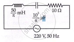
The net impedance of circuit (as shown in figure) will be ______.
When a capacitor is connected in series LR circuit, the alternating current flowing in the circuit ______
