Advertisements
Advertisements
प्रश्न
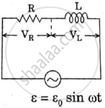
An LR circuit contains an inductor of 500 mH, a resistor of 25.0 Ω and an emf of 5.00 V in series. Find the potential difference across the resistor at t = (a) 20.0 ms, (b) 100 ms and (c) 1.00 s.
Advertisements
उत्तर
Given:-
Inductance of the inductor, L = 500 mH
Resistance of the resistor connected, R = 25 Ω
Emf of the battery, E = 5 V
For the given circuit, the potential difference across the resistance is given by
V = iR
The current in the LR circuit at time t is given by
i = i0 (1 − e−tR/L)
∴ Potential difference across the resistance at time t, V = (i0(1 − e−tR/L)R
(a) For t = 20 ms,
i = i0(1 − e−tR/L)
\[= \frac{E}{R}(1 - e^{- tR/L} )\]
\[ = \frac{5}{25}(1 - e^{- (2 \times {10}^{- 3} \times 25)/(500 \times {10}^{- 3} )} \]
\[ = \frac{1}{5}(1 - e^{- 1} ) = \frac{1}{5}(1 - 0 . 3678)\]
\[ = \frac{0 . 632}{5} = 0 . 1264 A\]
Potential difference:-
V = iR = (0.1264) × (25)
= 3.1606 V = 3.16 V
(b) For t = 100 ms,
i = i0(1 − e−tR/L)
\[= \frac{5}{25}\left( 1 - e^{( - 100 \times {10}^{- 3} ) \times (25/500 \times {10}^{- 3} )} \right)\]
\[ = \frac{1}{5}(1 - e^{- 50} )\]
\[ = \frac{1}{5}(1 - 0 . 0067)\]
\[ = \frac{0 . 9932}{5} = 0 . 19864 A\]
Potential difference:-
V = iR
= (0.19864) × (25) = 4.9665 = 4.97 V
(c) For t = 1 s,
\[i = \frac{5}{25}\left( 1 - e^{- 1 \times 25/500 \times {10}^{- 3}} \right)\]
\[ = \frac{1}{5}(1 - e^{- 50} )\]
\[ = \frac{1}{5} \times 1 = \frac{1}{5} A\]
Potential difference:-
V = iR
\[= \left( \frac{1}{5} \times 25 \right) = 5 V\]
APPEARS IN
संबंधित प्रश्न
(i) Find the value of the phase difference between the current and the voltage in the series LCR circuit shown below. Which one leads in phase : current or voltage ?
(ii) Without making any other change, find the value of the additional capacitor C1, to be connected in parallel with the capacitor C, in order to make the power factor of the circuit unity.

A source of ac voltage v = v0 sin ωt, is connected across a pure inductor of inductance L. Derive the expressions for the instantaneous current in the circuit. Show that average power dissipated in the circuit is zero.
Show that in an a.c. circuit containing a pure inductor, the voltage is ahead of current by π/2 in phase ?
A series LCR circuit is connected to a source having voltage v = vm sin ωt. Derive the expression for the instantaneous current I and its phase relationship to the applied voltage.
Obtain the condition for resonance to occur. Define ‘power factor’. State the conditions under which it is (i) maximum and (ii) minimum.
An L-R circuit has L = 1.0 H and R = 20 Ω. It is connected across an emf of 2.0 V at t = 0. Find di/dt at (a) t = 100 ms, (b) t = 200 ms and (c) t = 1.0 s.
An LR circuit having a time constant of 50 ms is connected with an ideal battery of emf ε. find the time elapsed before (a) the current reaches half its maximum value, (b) the power dissipated in heat reaches half its maximum value and (c) the magnetic field energy stored in the circuit reaches half its maximum value.
An ac circuit as shown in the figure has an inductor of inductance L and a resistor or resistance R connected in series. Using the phasor diagram, explain why the voltage in the circuit will lead the current in phase.
The potential difference across the resistor is 160V and that across the inductor is 120V. Find the effective value of the applied voltage. If the effective current in the circuit be 1.0 A, calculate the total impedance of the circuit.
What will be the potential difference in the circuit when direct current is passed through the circuit?
Using the phasor diagram, derive the expression for the current flowing in an ideal inductor connected to an a.c. source of voltage, v= vo sin ωt. Hence plot graphs showing the variation of (i) applied voltage and (ii) the current as a function of ωt.
The selectivity of a series LCR a.c. circuit is large, when ______.
Choose the correct answer from given options
The phase difference between the current and the voltage in series LCR circuit at resonance is
A series LCR circuit with L = 0.12 H, C = 480 nF, R = 23 Ω is connected to a 230 V variable frequency supply.
(a) What is the source frequency for which current amplitude is maximum. Obtain this maximum value.
(b) What is the source frequency for which average power absorbed by the circuit is maximum. Obtain the value of this maximum power.
(c) For which frequencies of the source is the power transferred to the circuit half the power at resonant frequency? What is the current amplitude at these frequencies?
(d) What is the Q-factor of the given circuit?
In an L.C.R. series a.c. circuit, the current ______.
A coil of 40 henry inductance is connected in series with a resistance of 8 ohm and the combination is joined to the terminals of a 2 volt battery. The time constant of the circuit is ______.
The phase diffn b/w the current and voltage at resonance is
Define Impedance.
A series LCR circuit containing a resistance of 120 Ω has angular resonance frequency 4 × 10⁵ rad s-1. At resonance the voltage across resistance and inductance are 60 V and 40 V respectively. At what frequency the current in the circuit lags the voltage by 45°. Give answer in ______ × 105 rad s-1.
A series RL circuit with R = 10 Ω and L = `(100/pi)` mH is connected to an ac source of voltage V = 141 sin (100 πt), where V is in volts and t is in seconds. Calculate
- the impedance of the circuit
- phase angle, and
- the voltage drop across the inductor.
A 20Ω resistance, 10 mH inductance coil and 15µF capacitor are joined in series. When a suitable frequency alternating current source is joined to this combination, the circuit resonates. If the resistance is made \[\frac {1}{3}\] rd, the resonant frequency ______.
