Advertisements
Advertisements
प्रश्न
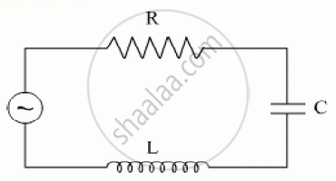
A series LCR circuit is connected to an ac source. Using the phasor diagram, derive the expression for the impedance of the circuit.
Advertisements
उत्तर
 LCR Circuit |
 |
E = E0 sinωt is applied to a series LCR circuit. Since all three of them are connected in series the current through them is the same. But the voltage across each element has a different phase relation with the current.
The potential difference VL, VC and VR across L, C and R at any instant is given by VL = IXL, VC = IXC and VR = IR, where I is the current at that instant.
VR is in phase with I. VL leads I by 90° and VC lags behind I by 90° so the phasor diagram will be as shown Assuming VL > VC, the applied emf E which is equal to the resultant of the potential drop across R, L & C is given as
`E^2 = I^2[R^2 + (X_L - X_C)^2]`
Or I = `E/sqrt[[R^2 + (X_L - X_C)^2]` = `E/Z`, Where Z is Impedance.
Emf leads current by a phase angle φ as `tanφ = (V_L - V_C)/R = (X_L - X_C)/R`
APPEARS IN
संबंधित प्रश्न
The figure shows a series LCR circuit with L = 10.0 H, C = 40 μF, R = 60 Ω connected to a variable frequency 240 V source, calculate
(i) the angular frequency of the source which drives the circuit at resonance,
(ii) the current at the resonating frequency,
(iii) the rms potential drop across the inductor at resonance.
Derive an expression for the average power consumed in a series LCR circuit connected to a.c. source in which the phase difference between the voltage and the current in the circuit is Φ.
A coil of resistance 40 Ω is connected across a 4.0 V battery. 0.10 s after the battery is connected, the current in the coil is 63 mA. Find the inductance of the coil.
For a series LCR-circuit, the power loss at resonance is ______.
Which of the following components of an LCR circuit, with a.c. supply, dissipates energy?
A series LCR circuit containing a 5.0 H inductor, 80 µF capacitors, and 40 Ω resistor is connected to a 230 V variable frequency ac source. The angular frequencies of the source at which power is transferred to the circuit are half the power at the resonant angular frequency are likely to be ______.
Which of the following statements about a series LCR circuit connected to an ac source is correct?
When an alternating voltage of 220V is applied across device X, a current of 0.25A flows which lags behind the applied voltage in phase by π/2 radian. If the same voltage is applied across another device Y, the same current flows but now it is in phase with the applied voltage.
- Name the devices X and Y.
- Calculate the current flowing in the circuit when the same voltage is applied across the series combination of X and Y.
Draw a labelled graph showing variation of impedance (Z) of a series LCR circuit Vs frequency (f) of the ac supply. Mark the resonant frequency as f0·
When a capacitor is connected in series LR circuit, the alternating current flowing in the circuit ______
