Advertisements
Advertisements
प्रश्न
Answer the following question.
In a series LCR circuit connected across an ac source of variable frequency, obtain the expression for its impedance and draw a plot showing its variation with frequency of the ac source.
Advertisements
उत्तर
Consider the LCR circuit
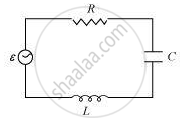
An AC source E with voltage `ν = ν_m` sin ωt is applied across LCR circuit
As the inductor, capacitor, and the resistor are connected in series so the current through all of them is the same (same amplitude and same phase)
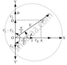
Let the current be 1= Im sin wt
The voltage across each component has a different phase relation with the current.
- Let the maximum voltage across the resistor be VR = ImR that is in the same phase of the current hence it is represented by OA in the phasor diagram.
- Let the maximum voltage across the inductor be VL = ImXL and that leads the current by `pi/2` it is represented by OD in the phasor diagram.
- Let the maximum voltage across the capacitor be Vc = ImXc and that lags behind the current by `pi/2`, it is represented by OC in the phasor diagram.
Resultant voltage can be found by using the vector sum of the phasors. The resultant voltage is represented by OF.
It can be written as:
`V_m = sqrt(V_R^2 + (V_L - V_c)^2)`
`V_m = sqrt((I_mR)^2 + (I_mX_L - I_mX_c)^2)`
`V_m = I_m sqrt(R^2 + (X_L - X_c)^2)`
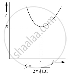
`Z = V_m/I_m = sqrt(R^2 + (X_L - X_c)^2)`
or, `Z = V_m/I_m = sqrt(R^2 + (ωL - 1/(ωC))^2)`
Variation of impedance Z with frequency f:
संबंधित प्रश्न
In a series LCR circuit, obtain the condition under which watt-less current flows in the circuit ?
An inductor-coil of resistance 10 Ω and inductance 120 mH is connected across a battery of emf 6 V and internal resistance 2 Ω. Find the charge which flows through the inductor in (a) 10 ms, (b) 20 ms and (c) 100 ms after the connections are made.
An ac circuit as shown in the figure has an inductor of inductance L and a resistor or resistance R connected in series. Using the phasor diagram, explain why the voltage in the circuit will lead the current in phase.
In series combination of R, L and C with an A.C. source at resonance, if R = 20 ohm, then impedence Z of the combination is ______.
In a series LCR circuit the voltage across an inductor, capacitor and resistor are 20 V, 20 V and 40 V respectively. The phase difference between the applied voltage and the current in the circuit is ______.
At resonant frequency the current amplitude in series LCR circuit is ______.
Draw the impedance triangle for a series LCR AC circuit and write the expressions for the impedance and the phase difference between the emf and the current.
Select the most appropriate option with regard to resonance in a series LCR circuit.
Three students, X, Y and Z performed an experiment for studying the variation of ac with frequency in a series LCR circuit and obtained the graphs as shown below. They all used
- an AC source of the same emf and
- inductance of the same value.

- Who used minimum resistance?
- In which case will the quality Q factor be maximum?
- What did the students conclude about the nature of impedance at resonant frequency (f0)?
- An ideal capacitor is connected across 220 V, 50 Hz, and 220 V, 100 Hz supplies. Find the ratio of current flowing through it in the two cases.
