Advertisements
Advertisements
प्रश्न
Answer the following question.
In a series LCR circuit connected across an ac source of variable frequency, obtain the expression for its impedance and draw a plot showing its variation with frequency of the ac source.
Advertisements
उत्तर
Consider the LCR circuit
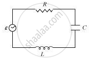
An AC source E with voltage `ν = ν_m` sin ωt is applied across LCR circuit
As the inductor, capacitor, and the resistor are connected in series so the current through all of them is the same (same amplitude and same phase)
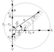
Let the current be 1= Im sin wt
The voltage across each component has a different phase relation with the current.
- Let the maximum voltage across the resistor be VR = ImR that is in the same phase of the current hence it is represented by OA in the phasor diagram.
- Let the maximum voltage across the inductor be VL = ImXL and that leads the current by `pi/2` it is represented by OD in the phasor diagram.
- Let the maximum voltage across the capacitor be Vc = ImXc and that lags behind the current by `pi/2`, it is represented by OC in the phasor diagram.
Resultant voltage can be found by using the vector sum of the phasors. The resultant voltage is represented by OF.
It can be written as:
`V_m = sqrt(V_R^2 + (V_L - V_c)^2)`
`V_m = sqrt((I_mR)^2 + (I_mX_L - I_mX_c)^2)`
`V_m = I_m sqrt(R^2 + (X_L - X_c)^2)`
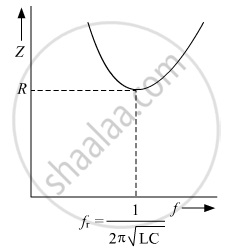
`Z = V_m/I_m = sqrt(R^2 + (X_L - X_c)^2)`
or, `Z = V_m/I_m = sqrt(R^2 + (ωL - 1/(ωC))^2)`
Variation of impedance Z with frequency f:
संबंधित प्रश्न
A series LCR circuit is connected across an a.c. source of variable angular frequency 'ω'. Plot a graph showing variation of current 'i' as a function of 'ω' for two resistances R1 and R2 (R1 > R2).
Answer the following questions using this graph :
(a) In which case is the resonance sharper and why?
(b) In which case in the power dissipation more and why?
A voltage V = V0 sin ωt is applied to a series LCR circuit. Derive the expression for the average power dissipated over a cycle. Under what condition (i) no power is dissipated even though the current flows through the circuit, (ii) maximum power is dissipated in the circuit?
A source of ac voltage v = v0 sin ωt, is connected across a pure inductor of inductance L. Derive the expressions for the instantaneous current in the circuit. Show that average power dissipated in the circuit is zero.
Use the expression for Lorentz force acting on the charge carriers of a conductor to obtain the expression for the induced emf across the conductor of length l moving with velocity v through a magnetic field B acting perpendicular to its length.
At resonance frequency the impedance in series LCR circuit is ______.
In series LCR AC-circuit, the phase angle between current and voltage is
For an LCR circuit driven at frequency ω, the equation reads
`L (di)/(dt) + Ri + q/C = v_i = v_m` sin ωt
- Multiply the equation by i and simplify where possible.
- Interpret each term physically.
- Cast the equation in the form of a conservation of energy statement.
- Integrate the equation over one cycle to find that the phase difference between v and i must be acute.
Which of the following combinations should be selected for better tuning of an L-C-R circuit used for communication?
A resistance of 200Ω and an inductor of \[\frac {1}{2π}\]Н are connected in series to a.c. voltage of 40 V and 100 Hz frequency. The phase angle between the voltage and current is ______.
When a capacitor is connected in series LR circuit, the alternating current flowing in the circuit ______
