Advertisements
Advertisements
प्रश्न
Answer the following question.
What is the phase difference between the voltages across the inductor and the capacitor at resonance in the LCR circuit?
Advertisements
उत्तर
It can be observed from the phasor diagram that the voltage across the inductor leads the current by `pi/2` and that along the capacitor leads the current by `pi/2`, so in every situation, the phase difference between the inductor and the capacitor is `pi`.
संबंधित प्रश्न
Define 'quality factor' of resonance in a series LCR circuit. What is its SI unit?
An LR circuit having a time constant of 50 ms is connected with an ideal battery of emf ε. find the time elapsed before (a) the current reaches half its maximum value, (b) the power dissipated in heat reaches half its maximum value and (c) the magnetic field energy stored in the circuit reaches half its maximum value.
In series combination of R, L and C with an A.C. source at resonance, if R = 20 ohm, then impedence Z of the combination is ______.
In an LCR circuit having L = 8 henery. C = 0.5 µF and R = 100 ohm in series, the resonance frequency in radian/sec is
If the rms current in a 50 Hz ac circuit is 5 A, the value of the current 1/300 seconds after its value becomes zero is ______.
In series LCR circuit, the plot of Imax vs ω is shown in figure. Find the bandwidth and mark in the figure.

Define Impedance.
When an alternating voltage of 220V is applied across device X, a current of 0.25A flows which lags behind the applied voltage in phase by π/2 radian. If the same voltage is applied across another device Y, the same current flows but now it is in phase with the applied voltage.
- Name the devices X and Y.
- Calculate the current flowing in the circuit when the same voltage is applied across the series combination of X and Y.
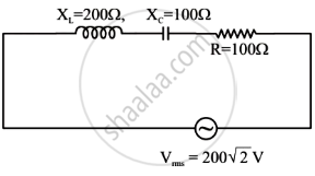
In the given circuit, rms value of current (Irms) through the resistor R is: