Advertisements
Advertisements
प्रश्न
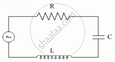
The figure shows a series LCR circuit with L = 10.0 H, C = 40 μF, R = 60 Ω connected to a variable frequency 240 V source, calculate
(i) the angular frequency of the source which drives the circuit at resonance,
(ii) the current at the resonating frequency,
(iii) the rms potential drop across the inductor at resonance.
Advertisements
उत्तर
(i) Resonant angular frequency
`omega_0 = 1/(sqrt(LC)) = 1/sqrt(10 xx 40 xx 10^6)`
`= 1/(sqrt (400 xx 10^-6 ))= 1/(20 xx 10^-3)`
`=1000/20`
`= 50 \text {rads}^-1`
(ii) At resonant frequency, we know that the inductive reactance cancels out the capacitive reactance.
The impedance = Z = 60Ω the value of resistance
The current amplitude at resonant frequency
`I_0 = E_0/Z = sqrt(2E_v)/R = (sqrt2 xx 240)/60`
` = 339.36/60 = 5.66A`
(iii) The R.M.S. value of current
`I_v = I_0/sqrt2 = 5.66/sqrt2 = 4A`
For R.M.S potential drop across inductor
`V_1 = I_VX_L`
`= I_V xx omega L`
`= 4 xx 50 xx 10`
`= 200 xx 10`
`= 2000 V`
APPEARS IN
संबंधित प्रश्न
In a series LCR circuit, obtain the condition under which the impedance of the circuit is minimum ?
An inductor-coil of inductance 17 mH is constructed from a copper wire of length 100 m and cross-sectional area 1 mm2. Calculate the time constant of the circuit if this inductor is joined across an ideal battery. The resistivity of copper = 1.7 × 10⁻⁸ Ω-m.
A solenoid having inductance 4.0 H and resistance 10 Ω is connected to a 4.0 V battery at t = 0. Find (a) the time constant, (b) the time elapsed before the current reaches 0.63 of its steady-state value, (c) the power delivered by the battery at this instant and (d) the power dissipated in Joule heating at this instant.
A constant current exists in an inductor-coil connected to a battery. The coil is short-circuited and the battery is removed. Show that the charge flown through the coil after the short-circuiting is the same as that which flows in one time constant before the short-circuiting.
Answer the following question.
What is the phase difference between the voltages across the inductor and the capacitor at resonance in the LCR circuit?
If an LCR series circuit is connected to an ac source, then at resonance the voltage across ______.
A coil of 0.01 henry inductance and 1 ohm resistance is connected to 200 volt, 50 Hz ac supply. Find the impedance of the circuit and time lag between max. alternating voltage and current.
Which of the following statements about a series LCR circuit connected to an ac source is correct?
Select the most appropriate option with regard to resonance in a series LCR circuit.
Out of the following which one is NOT the characteristic of LCR series resonant circuit?
