Advertisements
Advertisements
Question
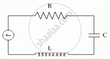
The figure shows a series LCR circuit with L = 10.0 H, C = 40 μF, R = 60 Ω connected to a variable frequency 240 V source, calculate
(i) the angular frequency of the source which drives the circuit at resonance,
(ii) the current at the resonating frequency,
(iii) the rms potential drop across the inductor at resonance.
Advertisements
Solution
(i) Resonant angular frequency
`omega_0 = 1/(sqrt(LC)) = 1/sqrt(10 xx 40 xx 10^6)`
`= 1/(sqrt (400 xx 10^-6 ))= 1/(20 xx 10^-3)`
`=1000/20`
`= 50 \text {rads}^-1`
(ii) At resonant frequency, we know that the inductive reactance cancels out the capacitive reactance.
The impedance = Z = 60Ω the value of resistance
The current amplitude at resonant frequency
`I_0 = E_0/Z = sqrt(2E_v)/R = (sqrt2 xx 240)/60`
` = 339.36/60 = 5.66A`
(iii) The R.M.S. value of current
`I_v = I_0/sqrt2 = 5.66/sqrt2 = 4A`
For R.M.S potential drop across inductor
`V_1 = I_VX_L`
`= I_V xx omega L`
`= 4 xx 50 xx 10`
`= 200 xx 10`
`= 2000 V`
APPEARS IN
RELATED QUESTIONS
A coil having an inductance L and a resistance R is connected to a battery of emf ε. Find the time taken for the magnetic energy stored in the circuit to change from one fourth of the steady-state value to half of the steady-state value.
The selectivity of a series LCR a.c. circuit is large, when ______.
Obtain the resonant frequency and Q-factor of a series LCR circuit with L = 3.0 H, C = 27 µF, and R = 7.4 Ω. It is desired to improve the sharpness of the resonance of the circuit by reducing its ‘full width at half maximum’ by a factor of 2. Suggest a suitable way.
If an LCR series circuit is connected to an ac source, then at resonance the voltage across ______.
At resonance frequency the impedance in series LCR circuit is ______.
The phase diffn b/w the current and voltage at resonance is
Draw the impedance triangle for a series LCR AC circuit and write the expressions for the impedance and the phase difference between the emf and the current.
To reduce the resonant frequency in an L-C-R series circuit with a generator ______.
To an ac power supply of 220 V at 50 Hz, a resistor of 20 Ω, a capacitor of reactance 25 Ω and an inductor of reactance 45 Ω are connected in series. The corresponding current in the circuit and the phase angle between the current and the voltage is respectively:
