Advertisements
Advertisements
प्रश्न
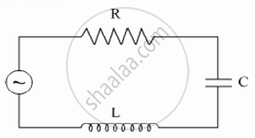
The figure shows a series LCR circuit with L = 10.0 H, C = 40 μF, R = 60 Ω connected to a variable frequency 240 V source, calculate
(i) the angular frequency of the source which drives the circuit at resonance,
(ii) the current at the resonating frequency,
(iii) the rms potential drop across the inductor at resonance.
Advertisements
उत्तर
(i) Resonant angular frequency
`omega_0 = 1/(sqrt(LC)) = 1/sqrt(10 xx 40 xx 10^6)`
`= 1/(sqrt (400 xx 10^-6 ))= 1/(20 xx 10^-3)`
`=1000/20`
`= 50 \text {rads}^-1`
(ii) At resonant frequency, we know that the inductive reactance cancels out the capacitive reactance.
The impedance = Z = 60Ω the value of resistance
The current amplitude at resonant frequency
`I_0 = E_0/Z = sqrt(2E_v)/R = (sqrt2 xx 240)/60`
` = 339.36/60 = 5.66A`
(iii) The R.M.S. value of current
`I_v = I_0/sqrt2 = 5.66/sqrt2 = 4A`
For R.M.S potential drop across inductor
`V_1 = I_VX_L`
`= I_V xx omega L`
`= 4 xx 50 xx 10`
`= 200 xx 10`
`= 2000 V`
APPEARS IN
संबंधित प्रश्न
In a series LCR circuit, VL = VC ≠ VR. What is the value of power factor?
An LR circuit contains an inductor of 500 mH, a resistor of 25.0 Ω and an emf of 5.00 V in series. Find the potential difference across the resistor at t = (a) 20.0 ms, (b) 100 ms and (c) 1.00 s.
An LR circuit having a time constant of 50 ms is connected with an ideal battery of emf ε. find the time elapsed before (a) the current reaches half its maximum value, (b) the power dissipated in heat reaches half its maximum value and (c) the magnetic field energy stored in the circuit reaches half its maximum value.
A coil having an inductance L and a resistance R is connected to a battery of emf ε. Find the time taken for the magnetic energy stored in the circuit to change from one fourth of the steady-state value to half of the steady-state value.
A series LCR circuit with R = 20 Ω, L = 1.5 H and C = 35 µF is connected to a variable-frequency 200 V ac supply. When the frequency of the supply equals the natural frequency of the circuit, what is the average power transferred to the circuit in one complete cycle?
In an LCR series a.c. circuit, the voltage across each of the components, L, C and R is 50V. The voltage across the LC combination will be ______.
At resonant frequency the current amplitude in series LCR circuit is ______.
As the frequency of an ac circuit increases, the current first increases and then decreases. What combination of circuit elements is most likely to comprise the circuit?
- Inductor and capacitor.
- Resistor and inductor.
- Resistor and capacitor.
- Resistor, inductor and capacitor.
Which of the following combinations should be selected for better tuning of an L-C-R circuit used for communication?
A 20Ω resistance, 10 mH inductance coil and 15µF capacitor are joined in series. When a suitable frequency alternating current source is joined to this combination, the circuit resonates. If the resistance is made \[\frac {1}{3}\] rd, the resonant frequency ______.
