Advertisements
Advertisements
Question
A coil having an inductance L and a resistance R is connected to a battery of emf ε. Find the time taken for the magnetic energy stored in the circuit to change from one fourth of the steady-state value to half of the steady-state value.
Advertisements
Solution
Given:-
Emf of the battery = ε
Inductance of the inductor = L
Resistance = R
Maximum current in the coil `= epsilon/R`
At the steady state, current in the coil, `i =epsilon/R.`
The magnetic field energy stored at the steady state is given by
\[U = \frac{1}{2}L i^2\text{ or } U\]
\[= \frac{\epsilon^2}{2 R^2}L\]
One-fourth of the steady-state value of the magnetic energy is given by
\[U' = \frac{1}{8}L\frac{E^2}{R^2}\]
Half of the value of the steady-state energy \[=\frac{1}{4}L\frac{E^2}{R^2}\]
Let the magnetic energy reach one-fourth of its steady-state value in time t1 and let it reach half of its value in time t2.
Now,
\[\frac{1}{8}L\frac{E^2}{R^2} = \frac{1}{2}L\frac{E^2}{R^2}(1 - e^{- t_1 R/L} )^2 \]
\[ \Rightarrow 1 - e^{- t_1 R/L} = \frac{1}{2}\]
\[ \Rightarrow t_1 \frac{R}{L} = \ln 2\]
And,
\[\frac{1}{4}L\frac{E^2}{R^2} = \frac{1}{2}L\frac{E^2}{R^2}(1 - e^{- t_2 R/L} )^2 \]
\[ \Rightarrow e^{- t_2 R/L} = \frac{\sqrt{2} - 1}{\sqrt{2}} = \frac{2 - \sqrt{2}}{2}\]
\[ \Rightarrow t_1 = \tau \ln\left( \frac{1}{2 - \sqrt{2}} \right) + \ln 2\]
Thus, the time taken by the magnetic energy stored in the circuit to change from one-fourth of its steady-state value to half of its steady-state value is given by
\[t_2 - t_1 = \tau \ln\frac{1}{2 - \sqrt{2}}\]
APPEARS IN
RELATED QUESTIONS
(i) Find the value of the phase difference between the current and the voltage in the series LCR circuit shown below. Which one leads in phase : current or voltage ?
(ii) Without making any other change, find the value of the additional capacitor C1, to be connected in parallel with the capacitor C, in order to make the power factor of the circuit unity.

In a series LCR circuit, obtain the condition under which watt-less current flows in the circuit ?
An L-R circuit has L = 1.0 H and R = 20 Ω. It is connected across an emf of 2.0 V at t = 0. Find di/dt at (a) t = 100 ms, (b) t = 200 ms and (c) t = 1.0 s.
An LR circuit having a time constant of 50 ms is connected with an ideal battery of emf ε. find the time elapsed before (a) the current reaches half its maximum value, (b) the power dissipated in heat reaches half its maximum value and (c) the magnetic field energy stored in the circuit reaches half its maximum value.
Draw a labelled graph showing a variation of impedance of a series LCR circuit with frequency of the a.c. supply.
Answer the following question.
What is the phase difference between the voltages across the inductor and the capacitor at resonance in the LCR circuit?
Use the expression for Lorentz force acting on the charge carriers of a conductor to obtain the expression for the induced emf across the conductor of length l moving with velocity v through a magnetic field B acting perpendicular to its length.
A series LCR circuit with R = 20 Ω, L = 1.5 H and C = 35 µF is connected to a variable-frequency 200 V ac supply. When the frequency of the supply equals the natural frequency of the circuit, what is the average power transferred to the circuit in one complete cycle?
Keeping the source frequency equal to the resonating frequency of the series LCR circuit, if the three elements, L, C and R are arranged in parallel, show that the total current in the parallel LCR circuit is minimum at this frequency. Obtain the current rms value in each branch of the circuit for the elements and source specified for this frequency.
A series LCR circuit with L = 0.12 H, C = 480 nF, R = 23 Ω is connected to a 230 V variable frequency supply.
(a) What is the source frequency for which current amplitude is maximum. Obtain this maximum value.
(b) What is the source frequency for which average power absorbed by the circuit is maximum. Obtain the value of this maximum power.
(c) For which frequencies of the source is the power transferred to the circuit half the power at resonant frequency? What is the current amplitude at these frequencies?
(d) What is the Q-factor of the given circuit?
The resonant frequency of a RF oscillator is 1 MHz and its bandwidth is 10 kHz. The quality factor will be :
Which of the following combinations should be selected for better tuning of an LCR circuit used for communication?
In series LCR circuit, the plot of Imax vs ω is shown in figure. Find the bandwidth and mark in the figure.

For an LCR circuit driven at frequency ω, the equation reads
`L (di)/(dt) + Ri + q/C = v_i = v_m` sin ωt
- Multiply the equation by i and simplify where possible.
- Interpret each term physically.
- Cast the equation in the form of a conservation of energy statement.
- Integrate the equation over one cycle to find that the phase difference between v and i must be acute.
Draw a labelled graph showing variation of impedance (Z) of a series LCR circuit Vs frequency (f) of the ac supply. Mark the resonant frequency as f0·
Three students, X, Y and Z performed an experiment for studying the variation of ac with frequency in a series LCR circuit and obtained the graphs as shown below. They all used
- an AC source of the same emf and
- inductance of the same value.

- Who used minimum resistance?
- In which case will the quality Q factor be maximum?
- What did the students conclude about the nature of impedance at resonant frequency (f0)?
- An ideal capacitor is connected across 220 V, 50 Hz, and 220 V, 100 Hz supplies. Find the ratio of current flowing through it in the two cases.
A series LCR circuit (L = 10 H, C = 10 µF, R = 50 Ω) is connected to V = 200 sin (100t). If ν0 is the resonant frequency and ν is the source frequency, then ______.
A resistance of 200Ω and an inductor of \[\frac {1}{2π}\]Н are connected in series to a.c. voltage of 40 V and 100 Hz frequency. The phase angle between the voltage and current is ______.
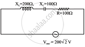
In the given circuit, rms value of current (Irms) through the resistor R is: