Advertisements
Advertisements
Question
A source of ac voltage v = v0 sin ωt, is connected across a pure inductor of inductance L. Derive the expressions for the instantaneous current in the circuit. Show that average power dissipated in the circuit is zero.
Advertisements
Solution
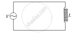
Using Kirchhoff’s loop rule in the above circuit,
\[V - L\frac{dI}{dt} = 0\]
\[\text { where, I is the instantaneous current flowing in the circuit }\]
\[ \Rightarrow L\frac{dI}{dt} = V_o \sin\omega t\]
\[ \Rightarrow \int dI = \frac{V_o}{L}\int\sin\omega tdt\]
\[ \Rightarrow I = \frac{V_o}{L}[ -\frac{\cos\omega t}{\omega}]\]
\[ \Rightarrow I = - \frac{V_o}{\omega L}\cos\omega t\]
\[ \Rightarrow I = \frac{V_o}{X_L}\sin(\omega t - \frac{\pi}{2})\]
\[\text { where, }X_L = \omega L = \text { inductance reactance }\]
\[ \therefore I = I_o \sin(\omega t - \frac{\pi}{2})\]
\[\text { where,} I_o = \frac{V_o}{X_L} =\text { peak value of ac}\]
\[\text { Now instantaneous power supplied by the source is } \]
\[P = VI = V_o I_o \sin\omega t \sin(\omega t - \frac{\pi}{2})\]
\[\text { Now the average power } ( P_{avg} ) \text { supplied over a complete cycle} ( 0 to 2\pi) \text { is }\]
\[ P_{avg} = \int_o^{2\pi} P = \int_o^{2\pi} V_o I_o \sin\theta \sin(\theta - \frac{\pi}{2})d\theta [\text { where } \theta = \omega t]\]
\[\text { Now over a complete cycle } \int_o^{2\pi} \sin\theta\sin(\theta - \frac{\pi}{2})d\theta = 0\]
\[\text { Therefore, }P_{avg} = \int_o^{2\pi} V_o I_o \text { sin }\theta\sin(\theta - \frac{\pi}{2})d\theta = 0\]
\[ P_{avg} = 0\]
Hence, the average power dissipated in the circuit is zero.
APPEARS IN
RELATED QUESTIONS
In a series LCR circuit, VL = VC ≠ VR. What is the value of power factor?
(i) Find the value of the phase difference between the current and the voltage in the series LCR circuit shown below. Which one leads in phase : current or voltage ?
(ii) Without making any other change, find the value of the additional capacitor C1, to be connected in parallel with the capacitor C, in order to make the power factor of the circuit unity.

Derive an expression for the average power consumed in a series LCR circuit connected to a.c. source in which the phase difference between the voltage and the current in the circuit is Φ.
A solenoid having inductance 4.0 H and resistance 10 Ω is connected to a 4.0 V battery at t = 0. Find (a) the time constant, (b) the time elapsed before the current reaches 0.63 of its steady-state value, (c) the power delivered by the battery at this instant and (d) the power dissipated in Joule heating at this instant.
A constant current exists in an inductor-coil connected to a battery. The coil is short-circuited and the battery is removed. Show that the charge flown through the coil after the short-circuiting is the same as that which flows in one time constant before the short-circuiting.
Answer the following question.
In a series LCR circuit connected across an ac source of variable frequency, obtain the expression for its impedance and draw a plot showing its variation with frequency of the ac source.
Derive an expression for the average power dissipated in a series LCR circuit.
To reduce the resonant frequency in an LCR series circuit with a generator
Define Impedance.
Draw a labelled graph showing variation of impedance (Z) of a series LCR circuit Vs frequency (f) of the ac supply. Mark the resonant frequency as f0·
