Advertisements
Advertisements
प्रश्न
A source of ac voltage v = v0 sin ωt, is connected across a pure inductor of inductance L. Derive the expressions for the instantaneous current in the circuit. Show that average power dissipated in the circuit is zero.
Advertisements
उत्तर
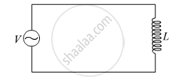
Using Kirchhoff’s loop rule in the above circuit,
\[V - L\frac{dI}{dt} = 0\]
\[\text { where, I is the instantaneous current flowing in the circuit }\]
\[ \Rightarrow L\frac{dI}{dt} = V_o \sin\omega t\]
\[ \Rightarrow \int dI = \frac{V_o}{L}\int\sin\omega tdt\]
\[ \Rightarrow I = \frac{V_o}{L}[ -\frac{\cos\omega t}{\omega}]\]
\[ \Rightarrow I = - \frac{V_o}{\omega L}\cos\omega t\]
\[ \Rightarrow I = \frac{V_o}{X_L}\sin(\omega t - \frac{\pi}{2})\]
\[\text { where, }X_L = \omega L = \text { inductance reactance }\]
\[ \therefore I = I_o \sin(\omega t - \frac{\pi}{2})\]
\[\text { where,} I_o = \frac{V_o}{X_L} =\text { peak value of ac}\]
\[\text { Now instantaneous power supplied by the source is } \]
\[P = VI = V_o I_o \sin\omega t \sin(\omega t - \frac{\pi}{2})\]
\[\text { Now the average power } ( P_{avg} ) \text { supplied over a complete cycle} ( 0 to 2\pi) \text { is }\]
\[ P_{avg} = \int_o^{2\pi} P = \int_o^{2\pi} V_o I_o \sin\theta \sin(\theta - \frac{\pi}{2})d\theta [\text { where } \theta = \omega t]\]
\[\text { Now over a complete cycle } \int_o^{2\pi} \sin\theta\sin(\theta - \frac{\pi}{2})d\theta = 0\]
\[\text { Therefore, }P_{avg} = \int_o^{2\pi} V_o I_o \text { sin }\theta\sin(\theta - \frac{\pi}{2})d\theta = 0\]
\[ P_{avg} = 0\]
Hence, the average power dissipated in the circuit is zero.
APPEARS IN
संबंधित प्रश्न
Derive an expression for the average power dissipated in a series LCR circuit.
Choose the correct answer from given options
The phase difference between the current and the voltage in series LCR circuit at resonance is
Keeping the source frequency equal to the resonating frequency of the series LCR circuit, if the three elements, L, C and R are arranged in parallel, show that the total current in the parallel LCR circuit is minimum at this frequency. Obtain the current rms value in each branch of the circuit for the elements and source specified for this frequency.
If an LCR series circuit is connected to an ac source, then at resonance the voltage across ______.
The phase diffn b/w the current and voltage at resonance is
Which of the following components of an LCR circuit, with a.c. supply, dissipates energy?
A series RL circuit with R = 10 Ω and L = `(100/pi)` mH is connected to an ac source of voltage V = 141 sin (100 πt), where V is in volts and t is in seconds. Calculate
- the impedance of the circuit
- phase angle, and
- the voltage drop across the inductor.
Draw a labelled graph showing variation of impedance (Z) of a series LCR circuit Vs frequency (f) of the ac supply. Mark the resonant frequency as f0·
A 20Ω resistance, 10 mH inductance coil and 15µF capacitor are joined in series. When a suitable frequency alternating current source is joined to this combination, the circuit resonates. If the resistance is made \[\frac {1}{3}\] rd, the resonant frequency ______.
