Advertisements
Advertisements
प्रश्न
A series RL circuit with R = 10 Ω and L = `(100/pi)` mH is connected to an ac source of voltage V = 141 sin (100 πt), where V is in volts and t is in seconds. Calculate
- the impedance of the circuit
- phase angle, and
- the voltage drop across the inductor.
Advertisements
उत्तर
Given:
R = 10 Ω
L = `(100/pi)` mH
V = 141 sin (100 π)t
From this equation, we get the value of ω = 100π and V = 141 volt
- To find: Impedance (Z)
Z = `sqrt(R^2 + X_L^2)`
Where Z is the impedance, R is the resistance, and XL is the impedance,
XL = ωL
XL = `(100pi xx 100)/(pi xx 10^-3)`
XL = 10Ω
Z = `sqrt(R^2 + X_L^2)`
Z = `sqrt((10)^2 + (10)^2)`
Z = `sqrt200`
Z = `10sqrt2`Ω - Phase Angle (Φ):
We can calculate the phase angle by the following formula,
`cosphi = R/Z`
`cosphi = 10/(10sqrt2)`
`cosphi = 1/sqrt2`
`phi = 45^circ` - Voltage drop:
`V_L = IX_L`
= `V/Z xx X_L`
`V_L = 141/(10sqrt2) xx 10`
`V_L = 141/sqrt2`
`V_L ≅ 100` volt
APPEARS IN
संबंधित प्रश्न
The magnetic field at a point inside a 2.0 mH inductor-coil becomes 0.80 of its maximum value in 20 µs when the inductor is joined to a battery. Find the resistance of the circuit.
Derive an expression for the average power dissipated in a series LCR circuit.
In an LCR series a.c. circuit, the voltage across each of the components, L, C and R is 50V. The voltage across the LC combination will be ______.
If the rms current in a 50 Hz ac circuit is 5 A, the value of the current 1/300 seconds after its value becomes zero is ______.
To reduce the resonant frequency in an LCR series circuit with a generator ______.
A series LCR circuit containing a resistance of 120 Ω has angular resonance frequency 4 × 10⁵ rad s-1. At resonance the voltage across resistance and inductance are 60 V and 40 V respectively. At what frequency the current in the circuit lags the voltage by 45°. Give answer in ______ × 105 rad s-1.
An alternating voltage of 220 V is applied across a device X. A current of 0.22 A flows in the circuit and it lags behind the applied voltage in phase by π/2 radian. When the same voltage is applied across another device Y, the current in the circuit remains the same and it is in phase with the applied voltage.
- Name the devices X and Y and,
- Calculate the current flowing in the circuit when the same voltage is applied across the series combination of X and Y.
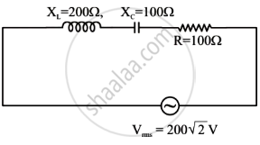
In the given circuit, rms value of current (Irms) through the resistor R is:
When a capacitor is connected in series LR circuit, the alternating current flowing in the circuit ______
