Advertisements
Advertisements
प्रश्न
A series LCR circuit is connected to a source having voltage v = vm sin ωt. Derive the expression for the instantaneous current I and its phase relationship to the applied voltage.
Obtain the condition for resonance to occur. Define ‘power factor’. State the conditions under which it is (i) maximum and (ii) minimum.
Advertisements
उत्तर
v = vm sin ωt
Let the current in the circuit be led the applied voltage by an angleΦ.
`i= i_m sin(omegat +phi)`
The Kirchhoff’s voltage law gives`L ((di)/dt +Ri +q/C = v)`.
It is given that v = vm sin ωt (applied voltage)
`L(d^2q)/(dt^2) +R(dq)/(dt) +q/C = v_m sinomegat ...... (1)`
On solving the equation, we obtain
`q = q_m sin(omegat + theta)`
`(dp)/(dt) = q_momega cos(omegat +theta)`
`((d^2)q)/(dt^2) = -q_momega^2 sin(omegat +theta)`
On substituting these values in equation (1), we obtain
`q_momega[R cos(omegat +theta)+ (X_c -X_L)sin(omegat +theta)] = v_msinomegat`
`X_c = 1/(omegaC) X_c = omegaL`
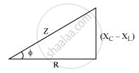
`Z = sqrt(R^2 +(X_c - X_L)^2`
`q_momegaZ[R/Z cos(omegat+theta)+((X_c -X_L))/Z sin (omegat+theta)] = v_m sin omegat ........... (2)`
Let `cos phi = R/2` and `(X_c -X_L)/Z = sinphi`
This gives
`tan phi = (X_c - X_L)/R`
On substituting this in equation (2), we obtain
`q_momegaZcos (omegat +theta -phi) = v_msinomegat`
On comparing the two sides, we obtain
`V_m = q_momegaZ = i+mZ`
`i_m = q_momega`
and `(theta-phi) = -pi/2`
`I = (dp)/(dt ) =q_momega cos (omegat+theta)`
`=i_m cos(omegat+theta)`
Or
`i = i_m sin(omegat +theta)`
Where,`i_m = (v_m)/Z = (v_m)/(sqrt(R^2 +(X_c - X_L)^2)`
And
`phi = tan^-1((X_c -X_L)/R)`
The condition for resonance to occur
`i_m = v_m/sqrt(R^2 +(X_C - X_L)^2)`
For resonance to occur, the value of im has to be the maximum.
The value of im will be the maximum when
`X_c = X_L`
`1/(omega C) = omegaL`
`omega^2 = 1/(LC)`
`omega = 1/(sqrtLC)`
`2pif = 1/sqrt(LC)`
`f = 1/(02pisqrt(LC)`
Power factor = cos Φ
Where,`cosphi = R/Z = R/(sqrt(R^2 +(X_c- X_L)^2)`
(i) Conditions for maximum power factor (i.e., cos Φ = 1)
-
XC = XL
Or
-
R = 0
(ii) Conditions for minimum power factor
-
When the circuit is purely inductive
-
When the circuit is purely capacitive
APPEARS IN
संबंधित प्रश्न
In a series LCR circuit, obtain the condition under which the impedance of the circuit is minimum ?
In a series LCR circuit, obtain the condition under which watt-less current flows in the circuit ?
The time constant of an LR circuit is 40 ms. The circuit is connected at t = 0 and the steady-state current is found to be 2.0 A. Find the current at (a) t = 10 ms (b) t = 20 ms, (c) t = 100 ms and (d) t = 1 s.
(i) An a.c. source of emf ε = 200 sin omegat is connected to a resistor of 50 Ω . calculate :
(1) Average current (`"I"_("avg")`)
(2) Root mean square (rms) value of emf
(ii) State any two characteristics of resonance in an LCR series circuit.
The selectivity of a series LCR a.c. circuit is large, when ______.
A series LCR circuit contains inductance 5 mH, capacitance 2µF and resistance ion. If a frequency A.C. source is varied, what is the frequency at which maximum power is dissipated?
A series LCR circuit containing a 5.0 H inductor, 80 µF capacitors, and 40 Ω resistor is connected to a 230 V variable frequency ac source. The angular frequencies of the source at which power is transferred to the circuit are half the power at the resonant angular frequency are likely to be ______.
When an alternating voltage of 220V is applied across device X, a current of 0.25A flows which lags behind the applied voltage in phase by π/2 radian. If the same voltage is applied across another device Y, the same current flows but now it is in phase with the applied voltage.
- Name the devices X and Y.
- Calculate the current flowing in the circuit when the same voltage is applied across the series combination of X and Y.
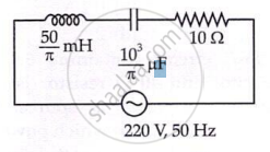
The net impedance of circuit (as shown in figure) will be ______.
Which of the following combinations should be selected for better tuning of an L-C-R circuit used for communication?
