Advertisements
Advertisements
प्रश्न
A series LCR circuit is connected to an ac source. Using the phasor diagram, derive the expression for the impedance of the circuit. Plot a graph to show the variation of current with frequency of the source, explaining the nature of its variation.
Advertisements
उत्तर
Let an alternating Emf E = E0 sinωt is applied to a series combination of inductor L, capacitor C and resistance R. Since all three of them are connected in series the current through them is same. But the voltage across each element has a different phase relation with current.

The potential difference VL, VC and VR across L, C and R at any instant is given by
VL = IXL, VC = IXC and VR = IR
Where I is the current at that instant.
XL is inductive reactance and
XC is capacitive reactance.
VR is in phase with I. VL leads I by 90° and VC lags behind I by 90°

In the phases diagram,
VL and VC are opposite to each other. If VL > VC then resultant (VL − VC) is represent by OD. OR represent the resultant of VR and (VL − VC). It is equal to the applied Emf E.
`E^2 = V_R^2 + (V_L -V_C)^2`
`E^2 =I^2 +[R^2+(X_L -X_c)^2]`
`or I =E/sqrt (R^2 + (X_2 -X_c)^2)`
The term `sqrt(R^2 +(X_2 - X_c))` is called impedance Z of the LCR circuit.
`Z = sqrt(R^2 +(X_2 -X_c)^2) =sqrt(R^2 +(L omega-1/(comega))^2)`
Emf leads current by a phase angle Φ
`tan phi = (V_L -V_C)/R = (X_L - X_c)/R =(Lomega -1/(comega))/R`
When resonance takes place
`omegaL= 1/(omegac)`
Impedance of circuit becomes equal to R. Current becomes maximum and is equal to `E/R`

`omega_0 = 1/sqrt(LC)`
`f_0 = omega_0/(2pi) = 1/(2pisqrt(LC))`
This is the condition for resonance.
When at resonance f = f0 the current in the circuit is maximum and hence impedance of the circuit is maximum for values of f less than or greater than f0 comparatively small current flames in the circuit.
संबंधित प्रश्न
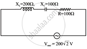
(i) Find the value of the phase difference between the current and the voltage in the series LCR circuit shown below. Which one leads in phase : current or voltage ?
(ii) Without making any other change, find the value of the additional capacitor C1, to be connected in parallel with the capacitor C, in order to make the power factor of the circuit unity.

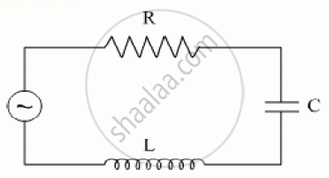
The figure shows a series LCR circuit with L = 10.0 H, C = 40 μF, R = 60 Ω connected to a variable frequency 240 V source, calculate
(i) the angular frequency of the source which drives the circuit at resonance,
(ii) the current at the resonating frequency,
(iii) the rms potential drop across the inductor at resonance.
Derive an expression for the average power consumed in a series LCR circuit connected to a.c. source in which the phase difference between the voltage and the current in the circuit is Φ.
Find the value of t/τ for which the current in an LR circuit builds up to (a) 90%, (b) 99% and (c) 99.9% of the steady-state value.
An LR circuit contains an inductor of 500 mH, a resistor of 25.0 Ω and an emf of 5.00 V in series. Find the potential difference across the resistor at t = (a) 20.0 ms, (b) 100 ms and (c) 1.00 s.
An inductor of inductance 2.00 H is joined in series with a resistor of resistance 200 Ω and a battery of emf 2.00 V. At t = 10 ms, find (a) the current in the circuit, (b) the power delivered by the battery, (c) the power dissipated in heating the resistor and (d) the rate at which energy is being stored in magnetic field.
Use the expression for Lorentz force acting on the charge carriers of a conductor to obtain the expression for the induced emf across the conductor of length l moving with velocity v through a magnetic field B acting perpendicular to its length.
Obtain the resonant frequency and Q-factor of a series LCR circuit with L = 3.0 H, C = 27 µF, and R = 7.4 Ω. It is desired to improve the sharpness of the resonance of the circuit by reducing its ‘full width at half maximum’ by a factor of 2. Suggest a suitable way.
If the rms current in a 50 Hz ac circuit is 5 A, the value of the current 1/300 seconds after its value becomes zero is ______.
In the given circuit, rms value of current (Irms) through the resistor R is: