Advertisements
Advertisements
प्रश्न
If the rms current in a 50 Hz ac circuit is 5 A, the value of the current 1/300 seconds after its value becomes zero is ______.
विकल्प
`5sqrt(2)` A
`5sqrt(3/2)` A
`5/6` A
`5/sqrt(2)` A
Advertisements
उत्तर
If the rms current in a 50 Hz ac circuit is 5 A, the value of the current 1/300 seconds after its value becomes zero is `underline(5sqrt(3/2) A)`.
Explanation:
Equation for i and V: Alternating current or voltage varying as sine function can be written as
`i = i_0 sin ωt = i_0 sin 2piv t = i_0 sin (2pi)/T t`

And `V = V_0 sin ωt = V_0 sin 2pivt = V_0 sin (2pi)/T t`
Where I and V are instantaneous values of current and voltage,
i0 and V0 are peak values of current and voltage
ω = Angular frequency on rad/sec, v = Frequency in Hz
T = TIme peroid
`I_(ωt) = I = sqrt(2)I_0 = 5sqrt(2)A`
`I = I_0 sin ωt`
At `t = 1/300 sec, I = 5sqrt(2) sin 2 pivt = 5sqrt(2) sin 2pi xx 50 xx 1/300`
= `5sqrt(2) sin pi/3 = 5sqrt(2) sin 60^circ`
= `52 - sqrt(3)sqrt(2)` = 532
= `5sqrt(3/2) A`
APPEARS IN
संबंधित प्रश्न
In a series LCR circuit, VL = VC ≠ VR. What is the value of power factor?
In a series LCR circuit, obtain the condition under which the impedance of the circuit is minimum ?
In a series LCR circuit, obtain the condition under which watt-less current flows in the circuit ?
An LR circuit contains an inductor of 500 mH, a resistor of 25.0 Ω and an emf of 5.00 V in series. Find the potential difference across the resistor at t = (a) 20.0 ms, (b) 100 ms and (c) 1.00 s.
An inductor-coil of resistance 10 Ω and inductance 120 mH is connected across a battery of emf 6 V and internal resistance 2 Ω. Find the charge which flows through the inductor in (a) 10 ms, (b) 20 ms and (c) 100 ms after the connections are made.
A coil having an inductance L and a resistance R is connected to a battery of emf ε. Find the time taken for the magnetic energy stored in the circuit to change from one fourth of the steady-state value to half of the steady-state value.
In a series, LCR circuit, obtain an expression for the resonant frequency.
Use the expression for Lorentz force acting on the charge carriers of a conductor to obtain the expression for the induced emf across the conductor of length l moving with velocity v through a magnetic field B acting perpendicular to its length.
Using the phasor diagram, derive the expression for the current flowing in an ideal inductor connected to an a.c. source of voltage, v= vo sin ωt. Hence plot graphs showing the variation of (i) applied voltage and (ii) the current as a function of ωt.
To reduce the resonant frequency in an LCR series circuit with a generator
Which of the following combinations should be selected for better tuning of an LCR circuit used for communication?
As the frequency of an ac circuit increases, the current first increases and then decreases. What combination of circuit elements is most likely to comprise the circuit?
- Inductor and capacitor.
- Resistor and inductor.
- Resistor and capacitor.
- Resistor, inductor and capacitor.
A series LCR circuit containing a resistance of 120 Ω has angular resonance frequency 4 × 10⁵ rad s-1. At resonance the voltage across resistance and inductance are 60 V and 40 V respectively. At what frequency the current in the circuit lags the voltage by 45°. Give answer in ______ × 105 rad s-1.
Draw the phasor diagram for a series LRC circuit connected to an AC source.
Draw the impedance triangle for a series LCR AC circuit and write the expressions for the impedance and the phase difference between the emf and the current.
Three students, X, Y and Z performed an experiment for studying the variation of ac with frequency in a series LCR circuit and obtained the graphs as shown below. They all used
- an AC source of the same emf and
- inductance of the same value.

- Who used minimum resistance?
- In which case will the quality Q factor be maximum?
- What did the students conclude about the nature of impedance at resonant frequency (f0)?
- An ideal capacitor is connected across 220 V, 50 Hz, and 220 V, 100 Hz supplies. Find the ratio of current flowing through it in the two cases.
In a series LCR circuit, the inductance L is 10 mH, capacitance C is 1 µF and resistance R is 100Ω. The frequency at which resonance occurs is ______.
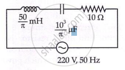
The net impedance of circuit (as shown in figure) will be ______.