Advertisements
Advertisements
प्रश्न
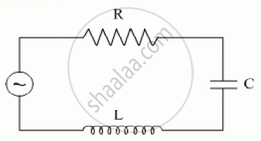
In a series, LCR circuit, obtain an expression for the resonant frequency.
Derive an expression for resonant frequency of series resonant circuit.
Advertisements
उत्तर
In a series LCR circuit,
I = `E/sqrt(R^2+(omega L - 1/(omega c))^2`
From this equation, we may observe that when ω = 0, I becomes 0, and again when ω = ∞, I = 0.
∴ This implies there must be a value of ω at which I is maximum.
So when I is maximum, `sqrt(R^2 + (omega L - 1/(omega c))^2` is minimum.
For this either R = 0, or `omega L - 1/(omega c)` = 0
So when `omega L -1/(omega c)` = 0, this is called the resonance condition.
∴ At resonance,
ωL = `1/(omega c)`
⇒ ω2 = `1/(L c)`
⇒ ωr = `1/sqrt(L c)`
⇒ 2 π fr = `1/sqrt(L c)`
∴ Frequency of resonance (fr) = `1/(2 pi) * 1/sqrt(L c)`
i.e., fr = `1/(2 pi) * 1/sqrt(L c)`
This is the required expression for resonant frequency.
संबंधित प्रश्न
The figure shows a series LCR circuit with L = 10.0 H, C = 40 μF, R = 60 Ω connected to a variable frequency 240 V source, calculate
(i) the angular frequency of the source which drives the circuit at resonance,
(ii) the current at the resonating frequency,
(iii) the rms potential drop across the inductor at resonance.
A series LCR circuit is connected to an ac source. Using the phasor diagram, derive the expression for the impedance of the circuit. Plot a graph to show the variation of current with frequency of the source, explaining the nature of its variation.
A series LCR circuit is connected to a source having voltage v = vm sin ωt. Derive the expression for the instantaneous current I and its phase relationship to the applied voltage.
Obtain the condition for resonance to occur. Define ‘power factor’. State the conditions under which it is (i) maximum and (ii) minimum.
Derive an expression for the average power consumed in a series LCR circuit connected to a.c. source in which the phase difference between the voltage and the current in the circuit is Φ.
An inductor-coil of inductance 17 mH is constructed from a copper wire of length 100 m and cross-sectional area 1 mm2. Calculate the time constant of the circuit if this inductor is joined across an ideal battery. The resistivity of copper = 1.7 × 10⁻⁸ Ω-m.
An LR circuit having a time constant of 50 ms is connected with an ideal battery of emf ε. find the time elapsed before (a) the current reaches half its maximum value, (b) the power dissipated in heat reaches half its maximum value and (c) the magnetic field energy stored in the circuit reaches half its maximum value.
A solenoid having inductance 4.0 H and resistance 10 Ω is connected to a 4.0 V battery at t = 0. Find (a) the time constant, (b) the time elapsed before the current reaches 0.63 of its steady-state value, (c) the power delivered by the battery at this instant and (d) the power dissipated in Joule heating at this instant.
The magnetic field at a point inside a 2.0 mH inductor-coil becomes 0.80 of its maximum value in 20 µs when the inductor is joined to a battery. Find the resistance of the circuit.
Two coils A and B have inductances 1.0 H and 2.0 H respectively. The resistance of each coil is 10 Ω. Each coil is connected to an ideal battery of emf 2.0 V at t = 0. Let iA and iBbe the currents in the two circuit at time t. Find the ratio iA / iB at (a) t = 100 ms, (b) t = 200 ms and (c) t = 1 s.
The current in a discharging LR circuit without the battery drops from 2.0 A to 1.0 A in 0.10 s. (a) Find the time constant of the circuit. (b) If the inductance of the circuit 4.0 H, what is its resistance?
Consider the circuit shown in figure. (a) Find the current through the battery a long time after the switch S is closed. (b) Suppose the switch is again opened at t = 0. What is the time constant of the discharging circuit? (c) Find the current through the inductor after one time constant.

Use the expression for Lorentz force acting on the charge carriers of a conductor to obtain the expression for the induced emf across the conductor of length l moving with velocity v through a magnetic field B acting perpendicular to its length.
Derive an expression for the average power dissipated in a series LCR circuit.
A series LCR circuit with L = 0.12 H, C = 480 nF, R = 23 Ω is connected to a 230 V variable frequency supply.
(a) What is the source frequency for which current amplitude is maximum. Obtain this maximum value.
(b) What is the source frequency for which average power absorbed by the circuit is maximum. Obtain the value of this maximum power.
(c) For which frequencies of the source is the power transferred to the circuit half the power at resonant frequency? What is the current amplitude at these frequencies?
(d) What is the Q-factor of the given circuit?
For a series LCR-circuit, the power loss at resonance is ______.
Assertion: When the frequency of the AC source in an LCR circuit equals the resonant frequency, the reactance of the circuit is zero, and so there is no current through the inductor or the capacitor.
Reason: The net current in the inductor and capacitor is zero.
In series LCR circuit, the phase angle between supply voltage and current is ______.
Which of the following components of an LCR circuit, with a.c. supply, dissipates energy?
A series LCR circuit containing a 5.0 H inductor, 80 µF capacitors, and 40 Ω resistor is connected to a 230 V variable frequency ac source. The angular frequencies of the source at which power is transferred to the circuit are half the power at the resonant angular frequency are likely to be ______.
For an LCR circuit driven at frequency ω, the equation reads
`L (di)/(dt) + Ri + q/C = v_i = v_m` sin ωt
- Multiply the equation by i and simplify where possible.
- Interpret each term physically.
- Cast the equation in the form of a conservation of energy statement.
- Integrate the equation over one cycle to find that the phase difference between v and i must be acute.
A series LCR circuit driven by 300 V at a frequency of 50 Hz contains a resistance R = 3 kΩ, an inductor of inductive reactance XL = 250 πΩ, and an unknown capacitor. The value of capacitance to maximize the average power should be ______.
A series LCR circuit containing a resistance of 120 Ω has angular resonance frequency 4 × 10⁵ rad s-1. At resonance the voltage across resistance and inductance are 60 V and 40 V respectively. At what frequency the current in the circuit lags the voltage by 45°. Give answer in ______ × 105 rad s-1.
When an alternating voltage of 220V is applied across device X, a current of 0.25A flows which lags behind the applied voltage in phase by π/2 radian. If the same voltage is applied across another device Y, the same current flows but now it is in phase with the applied voltage.
- Name the devices X and Y.
- Calculate the current flowing in the circuit when the same voltage is applied across the series combination of X and Y.
Select the most appropriate option with regard to resonance in a series LCR circuit.
Out of the following which one is NOT the characteristic of LCR series resonant circuit?
