Advertisements
Advertisements
प्रश्न
A series LCR circuit with R = 20 Ω, L = 1.5 H and C = 35 µF is connected to a variable-frequency 200 V ac supply. When the frequency of the supply equals the natural frequency of the circuit, what is the average power transferred to the circuit in one complete cycle?
Advertisements
उत्तर
At resonance, the frequency of the supply power equals the natural frequency of the given LCR circuit.
Resistance, R = 20 Ω
Inductance, L = 1.5 H
Capacitance, C = 35 μF = 35 × 10−6 F
AC supply voltage to the LCR circuit, V = 200 V
Impedance of the circuit is given by the relation,
`"Z" = sqrt("R"^2 + (ω"L" - 1/(ω"C"))^2)`
At resonance, ωL = `1/(ω"C")`
∴ Z = R = 20 Ω
Current in the circuit can be calculated as:
`"I" = "V"/"Z"`
= `200/20`
= 10 A
Hence, the average power transferred to the circuit in one complete cycle = VI = 200 × 10 = 2000 W.
संबंधित प्रश्न
Define 'quality factor' of resonance in a series LCR circuit. What is its SI unit?
(i) Find the value of the phase difference between the current and the voltage in the series LCR circuit shown below. Which one leads in phase : current or voltage ?
(ii) Without making any other change, find the value of the additional capacitor C1, to be connected in parallel with the capacitor C, in order to make the power factor of the circuit unity.

Show that in an a.c. circuit containing a pure inductor, the voltage is ahead of current by π/2 in phase ?
A series LCR circuit is connected to a source having voltage v = vm sin ωt. Derive the expression for the instantaneous current I and its phase relationship to the applied voltage.
Obtain the condition for resonance to occur. Define ‘power factor’. State the conditions under which it is (i) maximum and (ii) minimum.
A coil of resistance 40 Ω is connected across a 4.0 V battery. 0.10 s after the battery is connected, the current in the coil is 63 mA. Find the inductance of the coil.
An LR circuit contains an inductor of 500 mH, a resistor of 25.0 Ω and an emf of 5.00 V in series. Find the potential difference across the resistor at t = (a) 20.0 ms, (b) 100 ms and (c) 1.00 s.
Two coils A and B have inductances 1.0 H and 2.0 H respectively. The resistance of each coil is 10 Ω. Each coil is connected to an ideal battery of emf 2.0 V at t = 0. Let iA and iBbe the currents in the two circuit at time t. Find the ratio iA / iB at (a) t = 100 ms, (b) t = 200 ms and (c) t = 1 s.
(i) An a.c. source of emf ε = 200 sin omegat is connected to a resistor of 50 Ω . calculate :
(1) Average current (`"I"_("avg")`)
(2) Root mean square (rms) value of emf
(ii) State any two characteristics of resonance in an LCR series circuit.
Answer the following question.
What is the phase difference between the voltages across the inductor and the capacitor at resonance in the LCR circuit?
In an L.C.R. series a.c. circuit, the current ______.
If an LCR series circuit is connected to an ac source, then at resonance the voltage across ______.
In an LCR series a.c. circuit, the voltage across each of the components, L, C and R is 50V. The voltage across the LC combination will be ______.
A coil of 40 henry inductance is connected in series with a resistance of 8 ohm and the combination is joined to the terminals of a 2 volt battery. The time constant of the circuit is ______.
Which of the following combinations should be selected for better tuning of an LCR circuit used for communication?
A series RL circuit with R = 10 Ω and L = `(100/pi)` mH is connected to an ac source of voltage V = 141 sin (100 πt), where V is in volts and t is in seconds. Calculate
- the impedance of the circuit
- phase angle, and
- the voltage drop across the inductor.
Which of the following statements about a series LCR circuit connected to an ac source is correct?
Select the most appropriate option with regard to resonance in a series LCR circuit.
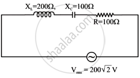
In the given circuit, rms value of current (Irms) through the resistor R is: