Advertisements
Advertisements
प्रश्न
Answer the following question.
Draw the diagram of a device that is used to decrease high ac voltage into a low ac voltage and state its working principle. Write four sources of energy loss in this device.
Advertisements
उत्तर
A transformer is a device that is used to either increase or decrease the ac voltage level. In order to decrease the high ac voltage level into a low ac voltage level we need a step-down transformer, whose diagram is as follows:

Working Principle:
A transformer works on the principle of electromagnetic induction. Alternating current in the primary coil produces a changing magnetic flux due to this an induced current is set up in the secondary coil. Losses in a transformer: Copper loss - The windings of the transformer have finite resistance due to which some energy is lost in the form of heat. It can be diminished using thick copper wires.
Iron loss - Loss is in the bulk of iron core due to the induced eddy currents in the iron core. It is minimized by using a thin laminated core.
Hysteresis loss - Alternating magnetizing and demagnetizing of the iron core causes the loss of energy in the form of heat. It is minimized using a special alloy of the iron core with silicon that has low hysteresis loss.
Magnetic loss - All the magnetic flux due to the primary coil does not pass through the secondary coil. So there is some leakage of flux. This loss can be minimized by winding primary over the secondary coil.
संबंधित प्रश्न
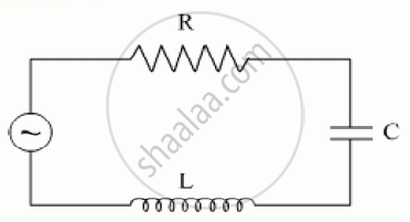
The figure shows a series LCR circuit with L = 10.0 H, C = 40 μF, R = 60 Ω connected to a variable frequency 240 V source, calculate
(i) the angular frequency of the source which drives the circuit at resonance,
(ii) the current at the resonating frequency,
(iii) the rms potential drop across the inductor at resonance.
A constant current exists in an inductor-coil connected to a battery. The coil is short-circuited and the battery is removed. Show that the charge flown through the coil after the short-circuiting is the same as that which flows in one time constant before the short-circuiting.
In an LCR series a.c. circuit, the voltage across each of the components, L, C and R is 50V. The voltage across the LC combination will be ______.
At resonance frequency the impedance in series LCR circuit is ______.
Which of the following components of an LCR circuit, with a.c. supply, dissipates energy?
In series LCR circuit, the plot of Imax vs ω is shown in figure. Find the bandwidth and mark in the figure.

A series LCR circuit containing a resistance of 120 Ω has angular resonance frequency 4 × 10⁵ rad s-1. At resonance the voltage across resistance and inductance are 60 V and 40 V respectively. At what frequency the current in the circuit lags the voltage by 45°. Give answer in ______ × 105 rad s-1.
A series RL circuit with R = 10 Ω and L = `(100/pi)` mH is connected to an ac source of voltage V = 141 sin (100 πt), where V is in volts and t is in seconds. Calculate
- the impedance of the circuit
- phase angle, and
- the voltage drop across the inductor.
Draw the phasor diagram for a series LRC circuit connected to an AC source.
Draw the impedance triangle for a series LCR AC circuit and write the expressions for the impedance and the phase difference between the emf and the current.
