Advertisements
Advertisements
प्रश्न
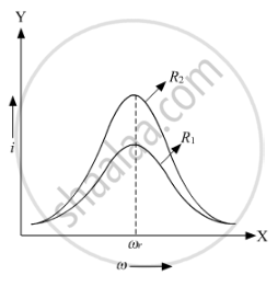
A series LCR circuit is connected across an a.c. source of variable angular frequency 'ω'. Plot a graph showing variation of current 'i' as a function of 'ω' for two resistances R1 and R2 (R1 > R2).
Answer the following questions using this graph :
(a) In which case is the resonance sharper and why?
(b) In which case in the power dissipation more and why?
Advertisements
उत्तर
he variation of current with angular frequency for the two resistances R1 and R2 is shown in the graph below.
Here,
i = Virtual current through the circuit
ω = Angular frequency of the source
ωr = Resonance frequency
From the graph, we can see that resonance for the resistance R2 is sharper than for R1 because resistance R2 is less than resistance R1. Therefore, at resonance, the value of peak current will rise more abruptly for a lower value of resistance.
b) Power associated with the resistance is given by
P=Ev Iv
where
Ev = Virtual voltage
Iv = Virtual current
From the graph, we can say that the virtual current in case of R2 is more than the virtual current in case of R1. Hence, the power dissipation in case of the circuit with R2 is more than that with R1.
APPEARS IN
संबंधित प्रश्न
Derive an expression for the average power consumed in a series LCR circuit connected to a.c. source in which the phase difference between the voltage and the current in the circuit is Φ.
Keeping the source frequency equal to the resonating frequency of the series LCR circuit, if the three elements, L, C and R are arranged in parallel, show that the total current in the parallel LCR circuit is minimum at this frequency. Obtain the current rms value in each branch of the circuit for the elements and source specified for this frequency.
In a series LCR circuit the voltage across an inductor, capacitor and resistor are 20 V, 20 V and 40 V respectively. The phase difference between the applied voltage and the current in the circuit is ______.
In series LCR circuit, the plot of Imax vs ω is shown in figure. Find the bandwidth and mark in the figure.

For an LCR circuit driven at frequency ω, the equation reads
`L (di)/(dt) + Ri + q/C = v_i = v_m` sin ωt
- Multiply the equation by i and simplify where possible.
- Interpret each term physically.
- Cast the equation in the form of a conservation of energy statement.
- Integrate the equation over one cycle to find that the phase difference between v and i must be acute.
A series LCR circuit containing a resistance of 120 Ω has angular resonance frequency 4 × 10⁵ rad s-1. At resonance the voltage across resistance and inductance are 60 V and 40 V respectively. At what frequency the current in the circuit lags the voltage by 45°. Give answer in ______ × 105 rad s-1.
A series RL circuit with R = 10 Ω and L = `(100/pi)` mH is connected to an ac source of voltage V = 141 sin (100 πt), where V is in volts and t is in seconds. Calculate
- the impedance of the circuit
- phase angle, and
- the voltage drop across the inductor.
Draw a labelled graph showing variation of impedance (Z) of a series LCR circuit Vs frequency (f) of the ac supply. Mark the resonant frequency as f0·
A series LCR circuit (L = 10 H, C = 10 µF, R = 50 Ω) is connected to V = 200 sin (100t). If ν0 is the resonant frequency and ν is the source frequency, then ______.
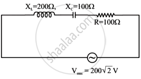
In the given circuit, rms value of current (Irms) through the resistor R is: