Advertisements
Advertisements
प्रश्न
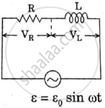
In series LCR circuit, the plot of Imax vs ω is shown in figure. Find the bandwidth and mark in the figure.

Advertisements
उत्तर
We know that bandwidth = (ω2 – ω1).
Where ω1 and ω2 are two frequencies where the current amplitude of LCR circuit becomes `12sqrt(12)` times (i.e., Irms) the value of current is maximum at resonant frequency.
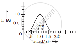
`I = E_0/sqrt(2) = 1/sqrt(2)` = 0.707 Amp
From graph ω1 and ω2 at 0.707A current is 0.8 and 1.2 rad/sec.
So Bandwith ω2.ω1 = 1.2 – 0.8 = 0.4 rad/sec.
APPEARS IN
संबंधित प्रश्न
A voltage V = V0 sin ωt is applied to a series LCR circuit. Derive the expression for the average power dissipated over a cycle. Under what condition (i) no power is dissipated even though the current flows through the circuit, (ii) maximum power is dissipated in the circuit?
A source of ac voltage v = v0 sin ωt, is connected across a pure inductor of inductance L. Derive the expressions for the instantaneous current in the circuit. Show that average power dissipated in the circuit is zero.
Find the value of t/τ for which the current in an LR circuit builds up to (a) 90%, (b) 99% and (c) 99.9% of the steady-state value.
The time constant of an LR circuit is 40 ms. The circuit is connected at t = 0 and the steady-state current is found to be 2.0 A. Find the current at (a) t = 10 ms (b) t = 20 ms, (c) t = 100 ms and (d) t = 1 s.
A coil having an inductance L and a resistance R is connected to a battery of emf ε. Find the time taken for the magnetic energy stored in the circuit to change from one fourth of the steady-state value to half of the steady-state value.
The magnetic field at a point inside a 2.0 mH inductor-coil becomes 0.80 of its maximum value in 20 µs when the inductor is joined to a battery. Find the resistance of the circuit.
Two coils A and B have inductances 1.0 H and 2.0 H respectively. The resistance of each coil is 10 Ω. Each coil is connected to an ideal battery of emf 2.0 V at t = 0. Let iA and iBbe the currents in the two circuit at time t. Find the ratio iA / iB at (a) t = 100 ms, (b) t = 200 ms and (c) t = 1 s.
A constant current exists in an inductor-coil connected to a battery. The coil is short-circuited and the battery is removed. Show that the charge flown through the coil after the short-circuiting is the same as that which flows in one time constant before the short-circuiting.
What will be the potential difference in the circuit when direct current is passed through the circuit?
In a series, LCR circuit, obtain an expression for the resonant frequency.
Answer the following question.
What is the phase difference between the voltages across the inductor and the capacitor at resonance in the LCR circuit?
If an LCR series circuit is connected to an ac source, then at resonance the voltage across ______.
Which of the following components of an LCR circuit, with a.c. supply, dissipates energy?
To reduce the resonant frequency in an LCR series circuit with a generator ______.
As the frequency of an ac circuit increases, the current first increases and then decreases. What combination of circuit elements is most likely to comprise the circuit?
- Inductor and capacitor.
- Resistor and inductor.
- Resistor and capacitor.
- Resistor, inductor and capacitor.
When an alternating voltage of 220V is applied across device X, a current of 0.25A flows which lags behind the applied voltage in phase by π/2 radian. If the same voltage is applied across another device Y, the same current flows but now it is in phase with the applied voltage.
- Name the devices X and Y.
- Calculate the current flowing in the circuit when the same voltage is applied across the series combination of X and Y.
A series LCR circuit is connected to an ac source. Using the phasor diagram, derive the expression for the impedance of the circuit.
Three students, X, Y and Z performed an experiment for studying the variation of ac with frequency in a series LCR circuit and obtained the graphs as shown below. They all used
- an AC source of the same emf and
- inductance of the same value.

- Who used minimum resistance?
- In which case will the quality Q factor be maximum?
- What did the students conclude about the nature of impedance at resonant frequency (f0)?
- An ideal capacitor is connected across 220 V, 50 Hz, and 220 V, 100 Hz supplies. Find the ratio of current flowing through it in the two cases.
Out of the following which one is NOT the characteristic of LCR series resonant circuit?
