Advertisements
Advertisements
प्रश्न
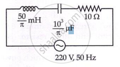
A voltage V = V0 sin ωt is applied to a series LCR circuit. Derive the expression for the average power dissipated over a cycle. Under what condition (i) no power is dissipated even though the current flows through the circuit, (ii) maximum power is dissipated in the circuit?
Advertisements
उत्तर
Voltage V=V0sinωt is applied to an series LCR circuit.
Current is π2" role="presentation" style="position: relative;">π2
`I_0=V_0/Z`
`phi=tan^(-1)((X_C-X_L)/R)`
Instantaneous power supplied by the source is
P=VI
=(V0sinωt)×(I0sin(ωt+ϕ)
`=(V_0I_0)/2[cosphi-cos(2omegat+phi)]`
The average power over a cycle is average of the two terms on the R.H.S of the above equation. The second term is time dependent; so, its average is zero.
`P=(V_0I_0)/2cosphi`
`=(V_0I_0)/(sqrt2sqr2)cosphi`
=VIcosϕ
P=I2Zcosϕ
cosϕ is called the power factor.
Case I
For pure inductive circuit or pure capacitive circuit, the phase difference between current and voltage is `pi/2`
`:.phi=pi/2,cosphi=0`
Therefore, no power is dissipated. This current is sometimes referred to as wattless current.
Case II
For power dissipated at resonance in an LCR circuit,
`X_C-X_L=0, phi=0`
∴ cos ϕ = 1
So, maximum power is dissipated.
APPEARS IN
संबंधित प्रश्न
In a series LCR circuit, obtain the condition under which the impedance of the circuit is minimum ?
An LR circuit with emf ε is connected at t = 0. (a) Find the charge Q which flows through the battery during 0 to t. (b) Calculate the work done by the battery during this period. (c) Find the heat developed during this period. (d) Find the magnetic field energy stored in the circuit at time t. (e) Verify that the results in the three parts above are consistent with energy conservation.
Answer the following question.
In a series LCR circuit connected across an ac source of variable frequency, obtain the expression for its impedance and draw a plot showing its variation with frequency of the ac source.
A series LCR circuit with R = 20 Ω, L = 1.5 H and C = 35 µF is connected to a variable-frequency 200 V ac supply. When the frequency of the supply equals the natural frequency of the circuit, what is the average power transferred to the circuit in one complete cycle?
Figure shows a series LCR circuit connected to a variable frequency 230 V source. L = 5.0 H, C = 80 µF, R = 40 Ω.

- Determine the source frequency which drives the circuit in resonance.
- Obtain the impedance of the circuit and the amplitude of current at the resonating frequency.
- Determine the rms potential drops across the three elements of the circuit. Show that the potential drop across the LC combination is zero at the resonating frequency.
Assertion: When the frequency of the AC source in an LCR circuit equals the resonant frequency, the reactance of the circuit is zero, and so there is no current through the inductor or the capacitor.
Reason: The net current in the inductor and capacitor is zero.
In series LCR AC-circuit, the phase angle between current and voltage is
To reduce the resonant frequency in an LCR series circuit with a generator ______.
The net impedance of circuit (as shown in figure) will be ______.
Which of the following combinations should be selected for better tuning of an L-C-R circuit used for communication?
