Advertisements
Advertisements
प्रश्न
An inductor of inductance 2.00 H is joined in series with a resistor of resistance 200 Ω and a battery of emf 2.00 V. At t = 10 ms, find (a) the current in the circuit, (b) the power delivered by the battery, (c) the power dissipated in heating the resistor and (d) the rate at which energy is being stored in magnetic field.
Advertisements
उत्तर
Given:-
Inductance of the inductor, L = 2 H
Resistance of the resistor connected to the inductor, R = 200 Ω,
Emf of the battery connected, E = 2 V
(a) The current in the LR circuit after t seconds after connecting the battery is given by
i = i0(1 − e−t/τ)
Here,
i0 = Steady state value of current
`i_0 = E/R=2/200A`
At time t = 10 ms, the current is given by
\[i= \frac{2}{200}(1 - e^{- 10 \times {10}^{- 3} \times 200/2} )\]
i = 0.01(1 − e−1)
i = 0.01(1 − 0.3678)
i = 0.01 × 0.632 = 6.3 mA
(b) The power delivered by the battery is given by
P = Vi
P = Ei0(1 − e−t/τ)
\[P = \frac{E^2}{R}(1 - e^{- t/\tau} )\]
\[P = \frac{2 \times 2}{200}(1 - e^{10 \times {10}^{- 3} \times 200/2} )\]
P = 0.02(1 − e−1)
P = 0.01264 = 12.6 mW
(c) The power dissipated in the resistor is given by
P1 = i2R
P1 = [i0(1 − e−t/τ)]2 R
P1 = (6.3 mA)2 × 200
P1 = 6.3 × 6.3 × 200 × 10−5
P1 = 79.38 × 10⁻⁴
P1 = 7.938 × 10−3 = 8 mW
(d) The rate at which the energy is stored in the magnetic field can be calculated as:-
\[W =\frac{1}{2}L i^2\]
\[W= \frac{L}{2} {i_0}^2 (1 - e^{- t/\tau} )^2\]
W = 2 × 10⁻²(0.225)
W = 0.455 × 10⁻²
W = 4.6 × 10⁻³
W = 4.6 mW
APPEARS IN
संबंधित प्रश्न
In a series LCR circuit, VL = VC ≠ VR. What is the value of power factor?
A source of ac voltage v = v0 sin ωt, is connected across a pure inductor of inductance L. Derive the expressions for the instantaneous current in the circuit. Show that average power dissipated in the circuit is zero.
A series LCR circuit is connected to a source having voltage v = vm sin ωt. Derive the expression for the instantaneous current I and its phase relationship to the applied voltage.
Obtain the condition for resonance to occur. Define ‘power factor’. State the conditions under which it is (i) maximum and (ii) minimum.
The time constant of an LR circuit is 40 ms. The circuit is connected at t = 0 and the steady-state current is found to be 2.0 A. Find the current at (a) t = 10 ms (b) t = 20 ms, (c) t = 100 ms and (d) t = 1 s.
An L-R circuit has L = 1.0 H and R = 20 Ω. It is connected across an emf of 2.0 V at t = 0. Find di/dt at (a) t = 100 ms, (b) t = 200 ms and (c) t = 1.0 s.
An LR circuit having a time constant of 50 ms is connected with an ideal battery of emf ε. find the time elapsed before (a) the current reaches half its maximum value, (b) the power dissipated in heat reaches half its maximum value and (c) the magnetic field energy stored in the circuit reaches half its maximum value.
A coil having an inductance L and a resistance R is connected to a battery of emf ε. Find the time taken for the magnetic energy stored in the circuit to change from one fourth of the steady-state value to half of the steady-state value.
A constant current exists in an inductor-coil connected to a battery. The coil is short-circuited and the battery is removed. Show that the charge flown through the coil after the short-circuiting is the same as that which flows in one time constant before the short-circuiting.
(i) An a.c. source of emf ε = 200 sin omegat is connected to a resistor of 50 Ω . calculate :
(1) Average current (`"I"_("avg")`)
(2) Root mean square (rms) value of emf
(ii) State any two characteristics of resonance in an LCR series circuit.
Draw a labelled graph showing a variation of impedance of a series LCR circuit with frequency of the a.c. supply.
Answer the following question.
Draw the diagram of a device that is used to decrease high ac voltage into a low ac voltage and state its working principle. Write four sources of energy loss in this device.
Derive an expression for the average power dissipated in a series LCR circuit.
Choose the correct answer from given options
The phase difference between the current and the voltage in series LCR circuit at resonance is
A coil of 40 henry inductance is connected in series with a resistance of 8 ohm and the combination is joined to the terminals of a 2 volt battery. The time constant of the circuit is ______.
To reduce the resonant frequency in an LCR series circuit with a generator
A series LCR circuit containing 5.0 H inductor, 80 µF capacitor and 40 Ω resistor is connected to 230 V variable frequency ac source. The angular frequencies of the source at which power transferred to the circuit is half the power at the resonant angular frequency are likely to be ______.
A series LCR circuit driven by 300 V at a frequency of 50 Hz contains a resistance R = 3 kΩ, an inductor of inductive reactance XL = 250 πΩ, and an unknown capacitor. The value of capacitance to maximize the average power should be ______.
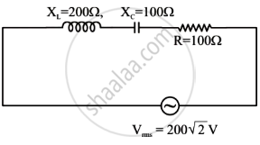
The net impedance of circuit (as shown in figure) will be ______.
A series LCR circuit (L = 10 H, C = 10 µF, R = 50 Ω) is connected to V = 200 sin (100t). If ν0 is the resonant frequency and ν is the source frequency, then ______.
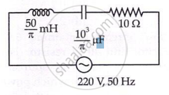
In the given circuit, rms value of current (Irms) through the resistor R is: