Advertisements
Advertisements
प्रश्न
Keeping the source frequency equal to the resonating frequency of the series LCR circuit, if the three elements, L, C and R are arranged in parallel, show that the total current in the parallel LCR circuit is minimum at this frequency. Obtain the current rms value in each branch of the circuit for the elements and source specified for this frequency.
Advertisements
उत्तर
An inductor (L), a capacitor (C), and a resistor (R) is connected in parallel with each other in a circuit where,
L = 5.0 H
C = 80 μF = 80 × 10−6 F
R = 40 Ω
Potential of the voltage source, V = 230 V
Impedance (Z) of the given parallel LCR circuit is given as:
`1/"Z" = sqrt(1/"R"^2 + (1/(ω"L") - ω"C")^2)`
Where,
ω = Angular frequency
At resonance, `1/(ω"L") - ω"C"` = 0
∴ ω = `1/sqrt("LC")`
= `1/(sqrt(5 xx 80 xx 10^-6))`
= 50 rad/s
Hence, the magnitude of Z is the maximum at 50 rad/s. As a result, the total current is minimum.
Rms current flowing through inductor L is given as:
IL = `"V"/(ω"L")`
= `230/(50 xx 5)`
= 0.92 A
Rms current flowing through capacitor C is given as:
IC = `"V"/(1/(ω"C")) = ω"CV"`
= 50 × 80 × 10−6 × 230
= 0.92 A
Rms current flowing through resistor R is given as:
IR = `"V"/"R"`
= `230/40`
= 5.75 A
APPEARS IN
संबंधित प्रश्न
Define 'quality factor' of resonance in a series LCR circuit. What is its SI unit?
A source of ac voltage v = v0 sin ωt, is connected across a pure inductor of inductance L. Derive the expressions for the instantaneous current in the circuit. Show that average power dissipated in the circuit is zero.
In a series LCR circuit, obtain the condition under which the impedance of the circuit is minimum ?
The figure shows a series LCR circuit with L = 10.0 H, C = 40 μF, R = 60 Ω connected to a variable frequency 240 V source, calculate
(i) the angular frequency of the source which drives the circuit at resonance,
(ii) the current at the resonating frequency,
(iii) the rms potential drop across the inductor at resonance.
Two coils A and B have inductances 1.0 H and 2.0 H respectively. The resistance of each coil is 10 Ω. Each coil is connected to an ideal battery of emf 2.0 V at t = 0. Let iA and iBbe the currents in the two circuit at time t. Find the ratio iA / iB at (a) t = 100 ms, (b) t = 200 ms and (c) t = 1 s.
A constant current exists in an inductor-coil connected to a battery. The coil is short-circuited and the battery is removed. Show that the charge flown through the coil after the short-circuiting is the same as that which flows in one time constant before the short-circuiting.
Using the phasor diagram, derive the expression for the current flowing in an ideal inductor connected to an a.c. source of voltage, v= vo sin ωt. Hence plot graphs showing the variation of (i) applied voltage and (ii) the current as a function of ωt.
For a series LCR-circuit, the power loss at resonance is ______.
A coil of 0.01 henry inductance and 1 ohm resistance is connected to 200 volt, 50 Hz ac supply. Find the impedance of the circuit and time lag between max. alternating voltage and current.
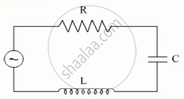
Consider the LCR circuit shown in figure. Find the net current i and the phase of i. Show that i = v/Z`. Find the impedance Z for this circuit.

A series LCR circuit driven by 300 V at a frequency of 50 Hz contains a resistance R = 3 kΩ, an inductor of inductive reactance XL = 250 πΩ, and an unknown capacitor. The value of capacitance to maximize the average power should be ______.
Which of the following statements about a series LCR circuit connected to an ac source is correct?
A series LCR circuit is connected to an ac source. Using the phasor diagram, derive the expression for the impedance of the circuit.
Draw the impedance triangle for a series LCR AC circuit and write the expressions for the impedance and the phase difference between the emf and the current.
Select the most appropriate option with regard to resonance in a series LCR circuit.
The net impedance of circuit (as shown in figure) will be ______.
Which of the following combinations should be selected for better tuning of an L-C-R circuit used for communication?
A resistance of 200Ω and an inductor of \[\frac {1}{2π}\]Н are connected in series to a.c. voltage of 40 V and 100 Hz frequency. The phase angle between the voltage and current is ______.
In the given circuit, rms value of current (Irms) through the resistor R is: