Advertisements
Advertisements
प्रश्न
To reduce the resonant frequency in an LCR series circuit with a generator ______.
विकल्प
the generator frequency should be reduced.
another capacitor should be added in parallel to the first.
the iron core of the inductor should be removed.
dielectric in the capacitor should be removed.
Advertisements
उत्तर
To reduce the resonant frequency in an LCR series circuit with a generator another capacitor should be added in parallel to the first.
Explanation:
At response XL = XC ⇒ ω0L = `1/(ω_0C)`
⇒ ω0 = `1/sqrt(LC) "rad"/sec`
⇒ v0 = `1/(2pisqrt(LC)) Hz`
Resonant frequency in an L-C-R circuit is given by
`v_0 = 1/(2pisqrt(LC))`
If L or C increases, the resonant frequency will reduce.
To increase capacitance, we must connect another capacitor parallel to the first.
APPEARS IN
संबंधित प्रश्न
In a series LCR circuit, obtain the condition under which the impedance of the circuit is minimum ?
A series LCR circuit is connected to an ac source. Using the phasor diagram, derive the expression for the impedance of the circuit. Plot a graph to show the variation of current with frequency of the source, explaining the nature of its variation.
The magnetic field at a point inside a 2.0 mH inductor-coil becomes 0.80 of its maximum value in 20 µs when the inductor is joined to a battery. Find the resistance of the circuit.
An inductor of inductance 2.00 H is joined in series with a resistor of resistance 200 Ω and a battery of emf 2.00 V. At t = 10 ms, find (a) the current in the circuit, (b) the power delivered by the battery, (c) the power dissipated in heating the resistor and (d) the rate at which energy is being stored in magnetic field.
Draw a labelled graph showing a variation of impedance of a series LCR circuit with frequency of the a.c. supply.
Answer the following question.
In a series LCR circuit connected across an ac source of variable frequency, obtain the expression for its impedance and draw a plot showing its variation with frequency of the ac source.
Answer the following question.
Draw the diagram of a device that is used to decrease high ac voltage into a low ac voltage and state its working principle. Write four sources of energy loss in this device.
Derive an expression for the average power dissipated in a series LCR circuit.
The selectivity of a series LCR a.c. circuit is large, when ______.
Choose the correct answer from given options
The phase difference between the current and the voltage in series LCR circuit at resonance is
Keeping the source frequency equal to the resonating frequency of the series LCR circuit, if the three elements, L, C and R are arranged in parallel, show that the total current in the parallel LCR circuit is minimum at this frequency. Obtain the current rms value in each branch of the circuit for the elements and source specified for this frequency.
In a series LCR circuit the voltage across an inductor, capacitor and resistor are 20 V, 20 V and 40 V respectively. The phase difference between the applied voltage and the current in the circuit is ______.
At resonant frequency the current amplitude in series LCR circuit is ______.
The resonant frequency of a RF oscillator is 1 MHz and its bandwidth is 10 kHz. The quality factor will be :
To reduce the resonant frequency in an LCR series circuit with a generator
Define Impedance.
An alternating voltage of 220 V is applied across a device X. A current of 0.22 A flows in the circuit and it lags behind the applied voltage in phase by π/2 radian. When the same voltage is applied across another device Y, the current in the circuit remains the same and it is in phase with the applied voltage.
- Name the devices X and Y and,
- Calculate the current flowing in the circuit when the same voltage is applied across the series combination of X and Y.
Select the most appropriate option with regard to resonance in a series LCR circuit.
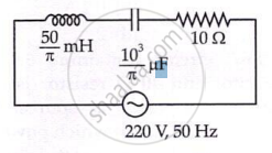
The net impedance of circuit (as shown in figure) will be ______.