Advertisements
Advertisements
प्रश्न
The time constant of an LR circuit is 40 ms. The circuit is connected at t = 0 and the steady-state current is found to be 2.0 A. Find the current at (a) t = 10 ms (b) t = 20 ms, (c) t = 100 ms and (d) t = 1 s.
Advertisements
उत्तर
Given:-
Time constant of the given LR circuit, τ = 40 ms
Steady-state current in the circuit, i0 = 2 A
(a) Current at time t = 10 ms:
i = i0(1 − e−t/τ)
= 2(1 − e−10/40)
= 2(1 − e−1/4)
= 2(1 − 0.7788)
= 0.4422 A
= 0.44 A
(b) Current at time t = 20 ms:
i = i0(1 − e−t/τ)
= 2(1 − e−20/40)
= 2(1 − e−1/2)
= 2(1 − 0.606)
= 0.788 A
= 0.79 A
(c) Current at t = 100 ms:
i = i0(1 − e−t/τ)
= 2(1 − e−100/40)
= 2(1 − e−10/4)
= 2(1 − e−5/2)
= 2(1−0.082)
=1.835 A
= 1.8 A
(d) Current at t = 1 s:
i = i0(1 − e−t/τ)
= 2(1 − e−1000/40)
= 2(1 − e−100/4)
= 2(1 − e−25)
= 2 × 1 A
= 2 A
APPEARS IN
संबंधित प्रश्न
In a series LCR circuit, VL = VC ≠ VR. What is the value of power factor?
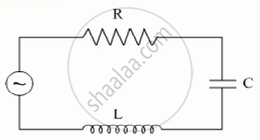
The figure shows a series LCR circuit with L = 10.0 H, C = 40 μF, R = 60 Ω connected to a variable frequency 240 V source, calculate
(i) the angular frequency of the source which drives the circuit at resonance,
(ii) the current at the resonating frequency,
(iii) the rms potential drop across the inductor at resonance.
A series LCR circuit is connected to an ac source. Using the phasor diagram, derive the expression for the impedance of the circuit. Plot a graph to show the variation of current with frequency of the source, explaining the nature of its variation.
Show that in an a.c. circuit containing a pure inductor, the voltage is ahead of current by π/2 in phase ?
An L-R circuit has L = 1.0 H and R = 20 Ω. It is connected across an emf of 2.0 V at t = 0. Find di/dt at (a) t = 100 ms, (b) t = 200 ms and (c) t = 1.0 s.
A coil having an inductance L and a resistance R is connected to a battery of emf ε. Find the time taken for the magnetic energy stored in the circuit to change from one fourth of the steady-state value to half of the steady-state value.
An LR circuit with emf ε is connected at t = 0. (a) Find the charge Q which flows through the battery during 0 to t. (b) Calculate the work done by the battery during this period. (c) Find the heat developed during this period. (d) Find the magnetic field energy stored in the circuit at time t. (e) Verify that the results in the three parts above are consistent with energy conservation.
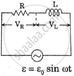
An ac circuit as shown in the figure has an inductor of inductance L and a resistor or resistance R connected in series. Using the phasor diagram, explain why the voltage in the circuit will lead the current in phase.
What will be the potential difference in the circuit when direct current is passed through the circuit?
Use the expression for Lorentz force acting on the charge carriers of a conductor to obtain the expression for the induced emf across the conductor of length l moving with velocity v through a magnetic field B acting perpendicular to its length.
The selectivity of a series LCR a.c. circuit is large, when ______.
In a series LCR circuit the voltage across an inductor, capacitor and resistor are 20 V, 20 V and 40 V respectively. The phase difference between the applied voltage and the current in the circuit is ______.
Which of the following combinations should be selected for better tuning of an LCR circuit used for communication?
As the frequency of an ac circuit increases, the current first increases and then decreases. What combination of circuit elements is most likely to comprise the circuit?
- Inductor and capacitor.
- Resistor and inductor.
- Resistor and capacitor.
- Resistor, inductor and capacitor.
A coil of 0.01 henry inductance and 1 ohm resistance is connected to 200 volt, 50 Hz ac supply. Find the impedance of the circuit and time lag between max. alternating voltage and current.
Select the most appropriate option with regard to resonance in a series LCR circuit.
Draw a labelled graph showing variation of impedance (Z) of a series LCR circuit Vs frequency (f) of the ac supply. Mark the resonant frequency as f0·
Which of the following combinations should be selected for better tuning of an L-C-R circuit used for communication?
