Advertisements
Advertisements
Question
The time constant of an LR circuit is 40 ms. The circuit is connected at t = 0 and the steady-state current is found to be 2.0 A. Find the current at (a) t = 10 ms (b) t = 20 ms, (c) t = 100 ms and (d) t = 1 s.
Advertisements
Solution
Given:-
Time constant of the given LR circuit, τ = 40 ms
Steady-state current in the circuit, i0 = 2 A
(a) Current at time t = 10 ms:
i = i0(1 − e−t/τ)
= 2(1 − e−10/40)
= 2(1 − e−1/4)
= 2(1 − 0.7788)
= 0.4422 A
= 0.44 A
(b) Current at time t = 20 ms:
i = i0(1 − e−t/τ)
= 2(1 − e−20/40)
= 2(1 − e−1/2)
= 2(1 − 0.606)
= 0.788 A
= 0.79 A
(c) Current at t = 100 ms:
i = i0(1 − e−t/τ)
= 2(1 − e−100/40)
= 2(1 − e−10/4)
= 2(1 − e−5/2)
= 2(1−0.082)
=1.835 A
= 1.8 A
(d) Current at t = 1 s:
i = i0(1 − e−t/τ)
= 2(1 − e−1000/40)
= 2(1 − e−100/4)
= 2(1 − e−25)
= 2 × 1 A
= 2 A
APPEARS IN
RELATED QUESTIONS
Define 'quality factor' of resonance in a series LCR circuit. What is its SI unit?
In a series LCR circuit connected to an a.c. source of voltage v = vmsinωt, use phasor diagram to derive an expression for the current in the circuit. Hence, obtain the expression for the power dissipated in the circuit. Show that power dissipated at resonance is maximum
A coil of resistance 40 Ω is connected across a 4.0 V battery. 0.10 s after the battery is connected, the current in the coil is 63 mA. Find the inductance of the coil.
A coil having an inductance L and a resistance R is connected to a battery of emf ε. Find the time taken for the magnetic energy stored in the circuit to change from one fourth of the steady-state value to half of the steady-state value.
Draw a labelled graph showing a variation of impedance of a series LCR circuit with frequency of the a.c. supply.
A series LCR circuit with R = 20 Ω, L = 1.5 H and C = 35 µF is connected to a variable-frequency 200 V ac supply. When the frequency of the supply equals the natural frequency of the circuit, what is the average power transferred to the circuit in one complete cycle?
A series LCR circuit with L = 0.12 H, C = 480 nF, R = 23 Ω is connected to a 230 V variable frequency supply.
(a) What is the source frequency for which current amplitude is maximum. Obtain this maximum value.
(b) What is the source frequency for which average power absorbed by the circuit is maximum. Obtain the value of this maximum power.
(c) For which frequencies of the source is the power transferred to the circuit half the power at resonant frequency? What is the current amplitude at these frequencies?
(d) What is the Q-factor of the given circuit?
Obtain the resonant frequency and Q-factor of a series LCR circuit with L = 3.0 H, C = 27 µF, and R = 7.4 Ω. It is desired to improve the sharpness of the resonance of the circuit by reducing its ‘full width at half maximum’ by a factor of 2. Suggest a suitable way.
If an LCR series circuit is connected to an ac source, then at resonance the voltage across ______.
Assertion: When the frequency of the AC source in an LCR circuit equals the resonant frequency, the reactance of the circuit is zero, and so there is no current through the inductor or the capacitor.
Reason: The net current in the inductor and capacitor is zero.
A series LCR circuit containing a 5.0 H inductor, 80 µF capacitors, and 40 Ω resistor is connected to a 230 V variable frequency ac source. The angular frequencies of the source at which power is transferred to the circuit are half the power at the resonant angular frequency are likely to be ______.
A series LCR circuit containing 5.0 H inductor, 80 µF capacitor and 40 Ω resistor is connected to 230 V variable frequency ac source. The angular frequencies of the source at which power transferred to the circuit is half the power at the resonant angular frequency are likely to be ______.
Define Impedance.
A series LCR circuit containing a resistance of 120 Ω has angular resonance frequency 4 × 10⁵ rad s-1. At resonance the voltage across resistance and inductance are 60 V and 40 V respectively. At what frequency the current in the circuit lags the voltage by 45°. Give answer in ______ × 105 rad s-1.
A series RL circuit with R = 10 Ω and L = `(100/pi)` mH is connected to an ac source of voltage V = 141 sin (100 πt), where V is in volts and t is in seconds. Calculate
- the impedance of the circuit
- phase angle, and
- the voltage drop across the inductor.
Which of the following statements about a series LCR circuit connected to an ac source is correct?
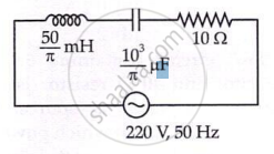
The net impedance of circuit (as shown in figure) will be ______.
To an ac power supply of 220 V at 50 Hz, a resistor of 20 Ω, a capacitor of reactance 25 Ω and an inductor of reactance 45 Ω are connected in series. The corresponding current in the circuit and the phase angle between the current and the voltage is respectively:
