Advertisements
Advertisements
Question
Consider the circuit shown in figure. (a) Find the current through the battery a long time after the switch S is closed. (b) Suppose the switch is again opened at t = 0. What is the time constant of the discharging circuit? (c) Find the current through the inductor after one time constant.

Advertisements
Solution
(a) Because the switch is closed, the battery gets connected across the L‒R circuit.
The current in the L‒R circuit after t seconds after connecting the battery is given by
i = i0 (1 − e−t/τ)
Here,
i0 = Steady state current
τ = Time constant = `L/R`
After a long time, t → ∞.
Now,
Current in the inductor, i = i0 (1 − e0) = 0
Thus, the effect of inductance vanishes.
\[i = \frac{\epsilon}{R_{net}}\]
\[i = \frac{\epsilon}{\frac{R_1 \times R_2}{R_1 + R_2}} = \frac{\epsilon( R_1 + R_2 )}{R_1 R_2}\]
(b) When the switch is opened, the resistance are in series.
The time constant is given by
\[\tau = \frac{L}{R_{net}} = \frac{L}{R_1 + R_2}\]
(c) The inductor will discharge through resistors R1 and R2.
The current through the inductor after one time constant is given by
t = τ
∴ Current, i = i0 e−τ/τ
Here,
\[i_0=\frac{\epsilon}{R_1 + R_2}\]
\[\therefore i=\frac{\epsilon}{R_1 + R_2} \times \frac{1}{e}\]
APPEARS IN
RELATED QUESTIONS
In a series LCR circuit, VL = VC ≠ VR. What is the value of power factor?
In a series LCR circuit, obtain the condition under which the impedance of the circuit is minimum ?
The figure shows a series LCR circuit with L = 10.0 H, C = 40 μF, R = 60 Ω connected to a variable frequency 240 V source, calculate
(i) the angular frequency of the source which drives the circuit at resonance,
(ii) the current at the resonating frequency,
(iii) the rms potential drop across the inductor at resonance.
A series LCR circuit is connected to an ac source. Using the phasor diagram, derive the expression for the impedance of the circuit. Plot a graph to show the variation of current with frequency of the source, explaining the nature of its variation.
The time constant of an LR circuit is 40 ms. The circuit is connected at t = 0 and the steady-state current is found to be 2.0 A. Find the current at (a) t = 10 ms (b) t = 20 ms, (c) t = 100 ms and (d) t = 1 s.
An LR circuit having a time constant of 50 ms is connected with an ideal battery of emf ε. find the time elapsed before (a) the current reaches half its maximum value, (b) the power dissipated in heat reaches half its maximum value and (c) the magnetic field energy stored in the circuit reaches half its maximum value.
The current in a discharging LR circuit without the battery drops from 2.0 A to 1.0 A in 0.10 s. (a) Find the time constant of the circuit. (b) If the inductance of the circuit 4.0 H, what is its resistance?
In a series, LCR circuit, obtain an expression for the resonant frequency.
Draw a labelled graph showing a variation of impedance of a series LCR circuit with frequency of the a.c. supply.
Figure shows a series LCR circuit connected to a variable frequency 230 V source. L = 5.0 H, C = 80 µF, R = 40 Ω.

- Determine the source frequency which drives the circuit in resonance.
- Obtain the impedance of the circuit and the amplitude of current at the resonating frequency.
- Determine the rms potential drops across the three elements of the circuit. Show that the potential drop across the LC combination is zero at the resonating frequency.
For a series LCR-circuit, the power loss at resonance is ______.
If an LCR series circuit is connected to an ac source, then at resonance the voltage across ______.
In a series LCR circuit the voltage across an inductor, capacitor and resistor are 20 V, 20 V and 40 V respectively. The phase difference between the applied voltage and the current in the circuit is ______.
The resonant frequency of a RF oscillator is 1 MHz and its bandwidth is 10 kHz. The quality factor will be :
A series LCR circuit containing 5.0 H inductor, 80 µF capacitor and 40 Ω resistor is connected to 230 V variable frequency ac source. The angular frequencies of the source at which power transferred to the circuit is half the power at the resonant angular frequency are likely to be ______.
As the frequency of an ac circuit increases, the current first increases and then decreases. What combination of circuit elements is most likely to comprise the circuit?
- Inductor and capacitor.
- Resistor and inductor.
- Resistor and capacitor.
- Resistor, inductor and capacitor.
A coil of 0.01 henry inductance and 1 ohm resistance is connected to 200 volt, 50 Hz ac supply. Find the impedance of the circuit and time lag between max. alternating voltage and current.
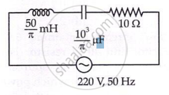
The net impedance of circuit (as shown in figure) will be ______.
Which of the following combinations should be selected for better tuning of an L-C-R circuit used for communication?
To an ac power supply of 220 V at 50 Hz, a resistor of 20 Ω, a capacitor of reactance 25 Ω and an inductor of reactance 45 Ω are connected in series. The corresponding current in the circuit and the phase angle between the current and the voltage is respectively:
