Advertisements
Advertisements
Question
As the frequency of an ac circuit increases, the current first increases and then decreases. What combination of circuit elements is most likely to comprise the circuit?
- Inductor and capacitor.
- Resistor and inductor.
- Resistor and capacitor.
- Resistor, inductor and capacitor.
Options
a and b
b and c
c and d
a and d
Advertisements
Solution
a and d
Explanation:
Compare the given circuit by predicting the variation in their reactances with frequency. So, that then we can decide the elements.
Reactance of an inductor of inductance L is XL = 2πvL, where v is the frequency of the AC circuit.

XC = Reactance of the capacitive circuit = `1/(2pi fC)`
With an increase in frequency `(f)` of an AC circuit, R remains constant, inductive reactance (XL) increases and capacitive reactance (XC) decreases.
For an L-C-R circuit,
Z = Impedance of the circuit
= `sqrt(R^2 + (X_L - X_C)^2)`
= `sqrt(R^2 + (2pivL - 1/(2pivC)^2)`
As frequency (v) increases, Z decreases and at certain value of the frequency known as resonant frequency (v0), impedance Z is minimum that is Zmin = R current varies inversely with impedance and at Zmin current is maximum.
APPEARS IN
RELATED QUESTIONS
In a series LCR circuit connected to an a.c. source of voltage v = vmsinωt, use phasor diagram to derive an expression for the current in the circuit. Hence, obtain the expression for the power dissipated in the circuit. Show that power dissipated at resonance is maximum
A voltage V = V0 sin ωt is applied to a series LCR circuit. Derive the expression for the average power dissipated over a cycle. Under what condition (i) no power is dissipated even though the current flows through the circuit, (ii) maximum power is dissipated in the circuit?
A series LCR circuit is connected to an ac source. Using the phasor diagram, derive the expression for the impedance of the circuit. Plot a graph to show the variation of current with frequency of the source, explaining the nature of its variation.
A series LCR circuit is connected to a source having voltage v = vm sin ωt. Derive the expression for the instantaneous current I and its phase relationship to the applied voltage.
Obtain the condition for resonance to occur. Define ‘power factor’. State the conditions under which it is (i) maximum and (ii) minimum.
An ac circuit as shown in the figure has an inductor of inductance L and a resistor or resistance R connected in series. Using the phasor diagram, explain why the voltage in the circuit will lead the current in phase.
Using the phasor diagram, derive the expression for the current flowing in an ideal inductor connected to an a.c. source of voltage, v= vo sin ωt. Hence plot graphs showing the variation of (i) applied voltage and (ii) the current as a function of ωt.
Derive an expression for the average power dissipated in a series LCR circuit.
Choose the correct answer from given options
The phase difference between the current and the voltage in series LCR circuit at resonance is
A series LCR circuit with L = 0.12 H, C = 480 nF, R = 23 Ω is connected to a 230 V variable frequency supply.
(a) What is the source frequency for which current amplitude is maximum. Obtain this maximum value.
(b) What is the source frequency for which average power absorbed by the circuit is maximum. Obtain the value of this maximum power.
(c) For which frequencies of the source is the power transferred to the circuit half the power at resonant frequency? What is the current amplitude at these frequencies?
(d) What is the Q-factor of the given circuit?
In a series LCR circuit supplied with AC, ______.
To reduce the resonant frequency in an LCR series circuit with a generator
In series LCR circuit, the plot of Imax vs ω is shown in figure. Find the bandwidth and mark in the figure.

A series LCR circuit containing a resistance of 120 Ω has angular resonance frequency 4 × 10⁵ rad s-1. At resonance the voltage across resistance and inductance are 60 V and 40 V respectively. At what frequency the current in the circuit lags the voltage by 45°. Give answer in ______ × 105 rad s-1.
When an alternating voltage of 220V is applied across device X, a current of 0.25A flows which lags behind the applied voltage in phase by π/2 radian. If the same voltage is applied across another device Y, the same current flows but now it is in phase with the applied voltage.
- Name the devices X and Y.
- Calculate the current flowing in the circuit when the same voltage is applied across the series combination of X and Y.
Select the most appropriate option with regard to resonance in a series LCR circuit.
Three students, X, Y and Z performed an experiment for studying the variation of ac with frequency in a series LCR circuit and obtained the graphs as shown below. They all used
- an AC source of the same emf and
- inductance of the same value.

- Who used minimum resistance?
- In which case will the quality Q factor be maximum?
- What did the students conclude about the nature of impedance at resonant frequency (f0)?
- An ideal capacitor is connected across 220 V, 50 Hz, and 220 V, 100 Hz supplies. Find the ratio of current flowing through it in the two cases.
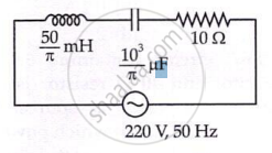
The net impedance of circuit (as shown in figure) will be ______.
A series LCR circuit (L = 10 H, C = 10 µF, R = 50 Ω) is connected to V = 200 sin (100t). If ν0 is the resonant frequency and ν is the source frequency, then ______.
To reduce the resonant frequency in an L-C-R series circuit with a generator ______.
