Advertisements
Advertisements
Questions
In a series, LCR circuit, obtain an expression for the resonant frequency.
Derive an expression for resonant frequency of series resonant circuit.
Advertisements
Solution
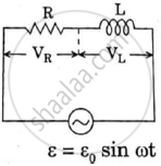
In a series LCR circuit,
I = `E/sqrt(R^2+(omega L - 1/(omega c))^2`
From this equation, we may observe that when ω = 0, I becomes 0, and again when ω = ∞, I = 0.
∴ This implies there must be a value of ω at which I is maximum.
So when I is maximum, `sqrt(R^2 + (omega L - 1/(omega c))^2` is minimum.
For this either R = 0, or `omega L - 1/(omega c)` = 0
So when `omega L -1/(omega c)` = 0, this is called the resonance condition.
∴ At resonance,
ωL = `1/(omega c)`
⇒ ω2 = `1/(L c)`
⇒ ωr = `1/sqrt(L c)`
⇒ 2 π fr = `1/sqrt(L c)`
∴ Frequency of resonance (fr) = `1/(2 pi) * 1/sqrt(L c)`
i.e., fr = `1/(2 pi) * 1/sqrt(L c)`
This is the required expression for resonant frequency.
RELATED QUESTIONS
Define 'quality factor' of resonance in a series LCR circuit. What is its SI unit?
In a series LCR circuit, obtain the condition under which watt-less current flows in the circuit ?
Show that in an a.c. circuit containing a pure inductor, the voltage is ahead of current by π/2 in phase ?
Find the value of t/τ for which the current in an LR circuit builds up to (a) 90%, (b) 99% and (c) 99.9% of the steady-state value.
A coil of resistance 40 Ω is connected across a 4.0 V battery. 0.10 s after the battery is connected, the current in the coil is 63 mA. Find the inductance of the coil.
The time constant of an LR circuit is 40 ms. The circuit is connected at t = 0 and the steady-state current is found to be 2.0 A. Find the current at (a) t = 10 ms (b) t = 20 ms, (c) t = 100 ms and (d) t = 1 s.
An L-R circuit has L = 1.0 H and R = 20 Ω. It is connected across an emf of 2.0 V at t = 0. Find di/dt at (a) t = 100 ms, (b) t = 200 ms and (c) t = 1.0 s.
An LR circuit contains an inductor of 500 mH, a resistor of 25.0 Ω and an emf of 5.00 V in series. Find the potential difference across the resistor at t = (a) 20.0 ms, (b) 100 ms and (c) 1.00 s.
An inductor-coil of inductance 17 mH is constructed from a copper wire of length 100 m and cross-sectional area 1 mm2. Calculate the time constant of the circuit if this inductor is joined across an ideal battery. The resistivity of copper = 1.7 × 10⁻⁸ Ω-m.
Two coils A and B have inductances 1.0 H and 2.0 H respectively. The resistance of each coil is 10 Ω. Each coil is connected to an ideal battery of emf 2.0 V at t = 0. Let iA and iBbe the currents in the two circuit at time t. Find the ratio iA / iB at (a) t = 100 ms, (b) t = 200 ms and (c) t = 1 s.
What will be the potential difference in the circuit when direct current is passed through the circuit?
Choose the correct answer from given options
The phase difference between the current and the voltage in series LCR circuit at resonance is
Figure shows a series LCR circuit connected to a variable frequency 230 V source. L = 5.0 H, C = 80 µF, R = 40 Ω.

- Determine the source frequency which drives the circuit in resonance.
- Obtain the impedance of the circuit and the amplitude of current at the resonating frequency.
- Determine the rms potential drops across the three elements of the circuit. Show that the potential drop across the LC combination is zero at the resonating frequency.
In an L.C.R. series a.c. circuit, the current ______.
At resonant frequency the current amplitude in series LCR circuit is ______.
A series LCR circuit contains inductance 5 mH, capacitance 2µF and resistance ion. If a frequency A.C. source is varied, what is the frequency at which maximum power is dissipated?
The resonant frequency of a RF oscillator is 1 MHz and its bandwidth is 10 kHz. The quality factor will be :
To reduce the resonant frequency in an LCR series circuit with a generator
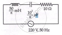
Consider the LCR circuit shown in figure. Find the net current i and the phase of i. Show that i = v/Z`. Find the impedance Z for this circuit.

A series LCR circuit containing a resistance of 120 Ω has angular resonance frequency 4 × 10⁵ rad s-1. At resonance the voltage across resistance and inductance are 60 V and 40 V respectively. At what frequency the current in the circuit lags the voltage by 45°. Give answer in ______ × 105 rad s-1.
Which of the following statements about a series LCR circuit connected to an ac source is correct?
Draw a labelled graph showing variation of impedance (Z) of a series LCR circuit Vs frequency (f) of the ac supply. Mark the resonant frequency as f0·
The net impedance of circuit (as shown in figure) will be ______.
A series LCR circuit (L = 10 H, C = 10 µF, R = 50 Ω) is connected to V = 200 sin (100t). If ν0 is the resonant frequency and ν is the source frequency, then ______.
A resistance of 200Ω and an inductor of \[\frac {1}{2π}\]Н are connected in series to a.c. voltage of 40 V and 100 Hz frequency. The phase angle between the voltage and current is ______.
When a capacitor is connected in series LR circuit, the alternating current flowing in the circuit ______
