Advertisements
Advertisements
Question
A coil of resistance 40 Ω is connected across a 4.0 V battery. 0.10 s after the battery is connected, the current in the coil is 63 mA. Find the inductance of the coil.
Advertisements
Solution
Given:-
Resistance, R = 40 Ω
Emf of the battery, E = 4 V
Now,
The steady-state current in the LR circuit is given by
\[i_0 = \frac{4}{40} = 0 . 1 A\]
At time, t = 0.1 s, the value of current i is 63 mA = 0.063 A
The current at time t is given by
i = i0(1 − e−t/τ)
⇒ 0.063 = 0.1(1 − e−tR/L)
⇒ 63 =100(1 − e−4/L)
⇒ 63 = 100(1 − e−4/L)
⇒ 1 − 0.63 = e−4/L
⇒ e−4/L = 0.37
\[\Rightarrow- \frac{4}{L}=\ln(0.37)\]
\[\Rightarrow L=\frac{- 4}{- 0 . 994}\]
= 4.024 H
= 4 H
APPEARS IN
RELATED QUESTIONS
In a series LCR circuit, VL = VC ≠ VR. What is the value of power factor?
The figure shows a series LCR circuit with L = 10.0 H, C = 40 μF, R = 60 Ω connected to a variable frequency 240 V source, calculate
(i) the angular frequency of the source which drives the circuit at resonance,
(ii) the current at the resonating frequency,
(iii) the rms potential drop across the inductor at resonance.
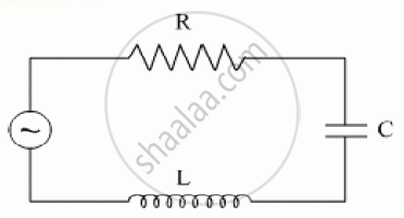
An ac circuit as shown in the figure has an inductor of inductance L and a resistor or resistance R connected in series. Using the phasor diagram, explain why the voltage in the circuit will lead the current in phase.
Answer the following question.
Draw the diagram of a device that is used to decrease high ac voltage into a low ac voltage and state its working principle. Write four sources of energy loss in this device.
Derive an expression for the average power dissipated in a series LCR circuit.
Choose the correct answer from given options
The phase difference between the current and the voltage in series LCR circuit at resonance is
A series LCR circuit with L = 0.12 H, C = 480 nF, R = 23 Ω is connected to a 230 V variable frequency supply.
(a) What is the source frequency for which current amplitude is maximum. Obtain this maximum value.
(b) What is the source frequency for which average power absorbed by the circuit is maximum. Obtain the value of this maximum power.
(c) For which frequencies of the source is the power transferred to the circuit half the power at resonant frequency? What is the current amplitude at these frequencies?
(d) What is the Q-factor of the given circuit?
In an LCR series a.c. circuit, the voltage across each of the components, L, C and R is 50V. The voltage across the LC combination will be ______.
A coil of 40 henry inductance is connected in series with a resistance of 8 ohm and the combination is joined to the terminals of a 2 volt battery. The time constant of the circuit is ______.
In series LCR circuit, the phase angle between supply voltage and current is ______.
In a series LCR circuit the voltage across an inductor, capacitor and resistor are 20 V, 20 V and 40 V respectively. The phase difference between the applied voltage and the current in the circuit is ______.
A series LCR circuit contains inductance 5 mH, capacitance 2µF and resistance ion. If a frequency A.C. source is varied, what is the frequency at which maximum power is dissipated?
The resonant frequency of a RF oscillator is 1 MHz and its bandwidth is 10 kHz. The quality factor will be :
To reduce the resonant frequency in an LCR series circuit with a generator
A series LCR circuit containing a resistance of 120 Ω has angular resonance frequency 4 × 10⁵ rad s-1. At resonance the voltage across resistance and inductance are 60 V and 40 V respectively. At what frequency the current in the circuit lags the voltage by 45°. Give answer in ______ × 105 rad s-1.
Which of the following statements about a series LCR circuit connected to an ac source is correct?
Draw the impedance triangle for a series LCR AC circuit and write the expressions for the impedance and the phase difference between the emf and the current.
A resistance of 200Ω and an inductor of \[\frac {1}{2π}\]Н are connected in series to a.c. voltage of 40 V and 100 Hz frequency. The phase angle between the voltage and current is ______.
To an ac power supply of 220 V at 50 Hz, a resistor of 20 Ω, a capacitor of reactance 25 Ω and an inductor of reactance 45 Ω are connected in series. The corresponding current in the circuit and the phase angle between the current and the voltage is respectively:
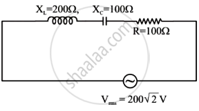
In the given circuit, rms value of current (Irms) through the resistor R is: