Advertisements
Advertisements
प्रश्न
As the frequency of an ac circuit increases, the current first increases and then decreases. What combination of circuit elements is most likely to comprise the circuit?
- Inductor and capacitor.
- Resistor and inductor.
- Resistor and capacitor.
- Resistor, inductor and capacitor.
पर्याय
a and b
b and c
c and d
a and d
Advertisements
उत्तर
a and d
Explanation:
Compare the given circuit by predicting the variation in their reactances with frequency. So, that then we can decide the elements.
Reactance of an inductor of inductance L is XL = 2πvL, where v is the frequency of the AC circuit.

XC = Reactance of the capacitive circuit = `1/(2pi fC)`
With an increase in frequency `(f)` of an AC circuit, R remains constant, inductive reactance (XL) increases and capacitive reactance (XC) decreases.
For an L-C-R circuit,
Z = Impedance of the circuit
= `sqrt(R^2 + (X_L - X_C)^2)`
= `sqrt(R^2 + (2pivL - 1/(2pivC)^2)`
As frequency (v) increases, Z decreases and at certain value of the frequency known as resonant frequency (v0), impedance Z is minimum that is Zmin = R current varies inversely with impedance and at Zmin current is maximum.
APPEARS IN
संबंधित प्रश्न
Define 'quality factor' of resonance in a series LCR circuit. What is its SI unit?
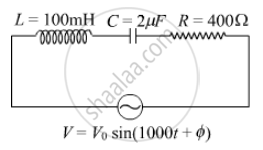
(i) Find the value of the phase difference between the current and the voltage in the series LCR circuit shown below. Which one leads in phase : current or voltage ?
(ii) Without making any other change, find the value of the additional capacitor C1, to be connected in parallel with the capacitor C, in order to make the power factor of the circuit unity.
Derive an expression for the average power consumed in a series LCR circuit connected to a.c. source in which the phase difference between the voltage and the current in the circuit is Φ.
The magnetic field at a point inside a 2.0 mH inductor-coil becomes 0.80 of its maximum value in 20 µs when the inductor is joined to a battery. Find the resistance of the circuit.
Derive an expression for the average power dissipated in a series LCR circuit.
Keeping the source frequency equal to the resonating frequency of the series LCR circuit, if the three elements, L, C and R are arranged in parallel, show that the total current in the parallel LCR circuit is minimum at this frequency. Obtain the current rms value in each branch of the circuit for the elements and source specified for this frequency.
A series LCR circuit with L = 0.12 H, C = 480 nF, R = 23 Ω is connected to a 230 V variable frequency supply.
(a) What is the source frequency for which current amplitude is maximum. Obtain this maximum value.
(b) What is the source frequency for which average power absorbed by the circuit is maximum. Obtain the value of this maximum power.
(c) For which frequencies of the source is the power transferred to the circuit half the power at resonant frequency? What is the current amplitude at these frequencies?
(d) What is the Q-factor of the given circuit?
In an L.C.R. series a.c. circuit, the current ______.
Assertion: When the frequency of the AC source in an LCR circuit equals the resonant frequency, the reactance of the circuit is zero, and so there is no current through the inductor or the capacitor.
Reason: The net current in the inductor and capacitor is zero.
A coil of 40 henry inductance is connected in series with a resistance of 8 ohm and the combination is joined to the terminals of a 2 volt battery. The time constant of the circuit is ______.
In series LCR circuit, the phase angle between supply voltage and current is ______.
The resonant frequency of a RF oscillator is 1 MHz and its bandwidth is 10 kHz. The quality factor will be :
The phase diffn b/w the current and voltage at resonance is
A series LCR circuit containing a 5.0 H inductor, 80 µF capacitors, and 40 Ω resistor is connected to a 230 V variable frequency ac source. The angular frequencies of the source at which power is transferred to the circuit are half the power at the resonant angular frequency are likely to be ______.
For an LCR circuit driven at frequency ω, the equation reads
`L (di)/(dt) + Ri + q/C = v_i = v_m` sin ωt
- Multiply the equation by i and simplify where possible.
- Interpret each term physically.
- Cast the equation in the form of a conservation of energy statement.
- Integrate the equation over one cycle to find that the phase difference between v and i must be acute.
A series LCR circuit (L = 10 H, C = 10 µF, R = 50 Ω) is connected to V = 200 sin (100t). If ν0 is the resonant frequency and ν is the source frequency, then ______.
A resistance of 200Ω and an inductor of \[\frac {1}{2π}\]Н are connected in series to a.c. voltage of 40 V and 100 Hz frequency. The phase angle between the voltage and current is ______.
To an ac power supply of 220 V at 50 Hz, a resistor of 20 Ω, a capacitor of reactance 25 Ω and an inductor of reactance 45 Ω are connected in series. The corresponding current in the circuit and the phase angle between the current and the voltage is respectively:
Out of the following which one is NOT the characteristic of LCR series resonant circuit?
