Advertisements
Advertisements
प्रश्न
Using the phasor diagram, derive the expression for the current flowing in an ideal inductor connected to an a.c. source of voltage, v= vo sin ωt. Hence plot graphs showing the variation of (i) applied voltage and (ii) the current as a function of ωt.
Advertisements
उत्तर

Figure (a) shows an ac source connected to an inductor. Usually, inductors have appreciable resistance in their windings, but we shall assume that this inductor has negligible resistance. Thus, the circuit is a purely inductive ac circuit. Let the voltage across the source be V = Vm sin ωt. Using the Kirchhoff’s loop rule, Σε (t) = 0, and since there is no resistor in the circuit,
`v - L(di)/(dt) = 0` ...(i)
where the second term is the self-induced Faraday emf in the inductor; and L is the self-inductance of the inductor. The negative sign follows from Lenz’s law.
From equation (i) we have
`(di)/(dt) = v/L = v_m/L sin ωt` ...(ii)
Equation (ii) implies that the equation for i(t), the current as a function of time, must be such that its slope di/dt is a sinusoidally varying quantity, with the same phase as the source voltage and an amplitude given by .vm/L
To obtain the current, we integrate di/dt with respect to time:
`int_ (d"i")/(d"t") d"t" = "v"_"m"/"L" int_ sin(wt)dt`
and get
`"i" = -("v"_"m")/(w"L") cos (wt) + cons tan t`
The integration constant has the dimension of current and is time-independent. Since the source has an emf which oscillates symmetrically about zero, the current it sustains also oscillates symmetrically about zero, so that no constant or time-independent component of the current exists. Therefore, the integration constant is zero.
Using
`-cos (wt) = sin(wt - pi/(2)), "we have"`
`"i" - "i"_"m" sin(wt - pi/(2))`
Where `"i"_"m" = ("v"_"m")/(w"L")` is the amplitude of the current.
The quantity ωL is analogous to the resistance and is called inductive reactance, denoted by XL :
`"X"_"L" = w"L"`
The amplitude of the current is, then
`"i"_"m" = ("v"_"m")/("X"_"L")`
The dimension of inductive reactance is the same as that of resistance and its SI unit is ohm (Ω). The inductive reactance limits the current in a purely inductive circuit in the same way as the resistance limits the current in a purely resistive circuit. The inductive reactance is directly proportional to the inductance and to the frequency of the current.

Fig. (b) A Phasor diagram for the circuit in Fig.(a) Fog. (c) Graph of v and i versus wt.
APPEARS IN
संबंधित प्रश्न
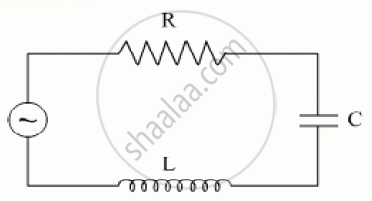
(i) Find the value of the phase difference between the current and the voltage in the series LCR circuit shown below. Which one leads in phase : current or voltage ?
(ii) Without making any other change, find the value of the additional capacitor C1, to be connected in parallel with the capacitor C, in order to make the power factor of the circuit unity.

The figure shows a series LCR circuit with L = 10.0 H, C = 40 μF, R = 60 Ω connected to a variable frequency 240 V source, calculate
(i) the angular frequency of the source which drives the circuit at resonance,
(ii) the current at the resonating frequency,
(iii) the rms potential drop across the inductor at resonance.
An L-R circuit has L = 1.0 H and R = 20 Ω. It is connected across an emf of 2.0 V at t = 0. Find di/dt at (a) t = 100 ms, (b) t = 200 ms and (c) t = 1.0 s.
An LR circuit contains an inductor of 500 mH, a resistor of 25.0 Ω and an emf of 5.00 V in series. Find the potential difference across the resistor at t = (a) 20.0 ms, (b) 100 ms and (c) 1.00 s.
(i) An a.c. source of emf ε = 200 sin omegat is connected to a resistor of 50 Ω . calculate :
(1) Average current (`"I"_("avg")`)
(2) Root mean square (rms) value of emf
(ii) State any two characteristics of resonance in an LCR series circuit.
In series LCR circuit, the phase angle between supply voltage and current is ______.
At resonant frequency the current amplitude in series LCR circuit is ______.
In series LCR AC-circuit, the phase angle between current and voltage is
When an alternating voltage of 220V is applied across device X, a current of 0.25A flows which lags behind the applied voltage in phase by π/2 radian. If the same voltage is applied across another device Y, the same current flows but now it is in phase with the applied voltage.
- Name the devices X and Y.
- Calculate the current flowing in the circuit when the same voltage is applied across the series combination of X and Y.
