Advertisements
Advertisements
प्रश्न
Use the expression for Lorentz force acting on the charge carriers of a conductor to obtain the expression for the induced emf across the conductor of length l moving with velocity v through a magnetic field B acting perpendicular to its length.
Advertisements
उत्तर
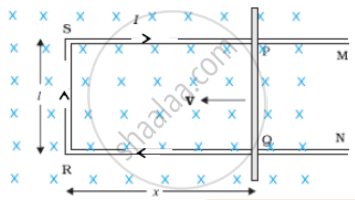
The arm PQ is moved to the left side, thus decreasing the area of the rectangular loop. This movement induces a current I as shown.
Let us consider a straight conductor moving in a uniform and time-independent magnetic field. The figure shows a rectangular conductor PQRS in which the conductor PQ is free to move. The rod PQ is moved towards the left with a constant velocity v as shown in the figure. Assume that there is no loss of energy due to friction. PQRS forms a closed circuit enclosing an area that changes as PQ moves. It is placed in a uniform magnetic field B which is perpendicular to the plane of this system. If the length RQ = x and RS l the magnetic flux ∅B enclosed by the loop PQRS will be
∅B = Blx
Since x is changing with time, the rate of change of flux φB will induce an emf given by:
`ε = -(d∅_B)/(dt) = - (d(Bl"x"))/(dt)`
= `-"B"l (d"x")/(d"t") = "B"l"v"`
where we have used dx/dt = – v which is the speed of the conductor PQ. The induced emf `"B"lv"` called motional emf. Thus, we are able to produce induced emf by moving a conductor instead of varying the magnetic field, that is, by changing the magnetic flux enclosed by the circuit. It is also possible to explain the motional emf expression by invoking the Lorentz force acting on the free charge carriers of conductor PQ. Consider any arbitrary charge q in the conductor PQ. When the rod moves with speed v, the charge will also be moving with speed v in the magnetic field B. The Lorentz force on this charge is qvB in magnitude, and its direction is towards Q. All charges experience the same force, in magnitude and direction, irrespective of their position in the rod PQ.
The work done in moving the charge from P to Q is,
`W = q"vB"l`
Since emf is the work done per unit charge,
`epsilon = "W"/q`
= `"B"l"v"`
This equation gives emf induced across the rod PQ
The total force on the charge at P is given by
`vec"F"= q(vec"E" + vec"v" xx vec"B")`
APPEARS IN
संबंधित प्रश्न
Derive an expression for the average power consumed in a series LCR circuit connected to a.c. source in which the phase difference between the voltage and the current in the circuit is Φ.
An inductor of inductance 2.00 H is joined in series with a resistor of resistance 200 Ω and a battery of emf 2.00 V. At t = 10 ms, find (a) the current in the circuit, (b) the power delivered by the battery, (c) the power dissipated in heating the resistor and (d) the rate at which energy is being stored in magnetic field.
The selectivity of a series LCR a.c. circuit is large, when ______.
A series LCR circuit with R = 20 Ω, L = 1.5 H and C = 35 µF is connected to a variable-frequency 200 V ac supply. When the frequency of the supply equals the natural frequency of the circuit, what is the average power transferred to the circuit in one complete cycle?
A series LCR circuit with L = 0.12 H, C = 480 nF, R = 23 Ω is connected to a 230 V variable frequency supply.
(a) What is the source frequency for which current amplitude is maximum. Obtain this maximum value.
(b) What is the source frequency for which average power absorbed by the circuit is maximum. Obtain the value of this maximum power.
(c) For which frequencies of the source is the power transferred to the circuit half the power at resonant frequency? What is the current amplitude at these frequencies?
(d) What is the Q-factor of the given circuit?
In series combination of R, L and C with an A.C. source at resonance, if R = 20 ohm, then impedence Z of the combination is ______.
If the rms current in a 50 Hz ac circuit is 5 A, the value of the current 1/300 seconds after its value becomes zero is ______.
A series LCR circuit containing a resistance of 120 Ω has angular resonance frequency 4 × 10⁵ rad s-1. At resonance the voltage across resistance and inductance are 60 V and 40 V respectively. At what frequency the current in the circuit lags the voltage by 45°. Give answer in ______ × 105 rad s-1.
Which of the following statements about a series LCR circuit connected to an ac source is correct?
Out of the following which one is NOT the characteristic of LCR series resonant circuit?
