Advertisements
Advertisements
प्रश्न
Use the expression for Lorentz force acting on the charge carriers of a conductor to obtain the expression for the induced emf across the conductor of length l moving with velocity v through a magnetic field B acting perpendicular to its length.
Advertisements
उत्तर
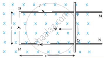
The arm PQ is moved to the left side, thus decreasing the area of the rectangular loop. This movement induces a current I as shown.
Let us consider a straight conductor moving in a uniform and time-independent magnetic field. The figure shows a rectangular conductor PQRS in which the conductor PQ is free to move. The rod PQ is moved towards the left with a constant velocity v as shown in the figure. Assume that there is no loss of energy due to friction. PQRS forms a closed circuit enclosing an area that changes as PQ moves. It is placed in a uniform magnetic field B which is perpendicular to the plane of this system. If the length RQ = x and RS l the magnetic flux ∅B enclosed by the loop PQRS will be
∅B = Blx
Since x is changing with time, the rate of change of flux φB will induce an emf given by:
`ε = -(d∅_B)/(dt) = - (d(Bl"x"))/(dt)`
= `-"B"l (d"x")/(d"t") = "B"l"v"`
where we have used dx/dt = – v which is the speed of the conductor PQ. The induced emf `"B"lv"` called motional emf. Thus, we are able to produce induced emf by moving a conductor instead of varying the magnetic field, that is, by changing the magnetic flux enclosed by the circuit. It is also possible to explain the motional emf expression by invoking the Lorentz force acting on the free charge carriers of conductor PQ. Consider any arbitrary charge q in the conductor PQ. When the rod moves with speed v, the charge will also be moving with speed v in the magnetic field B. The Lorentz force on this charge is qvB in magnitude, and its direction is towards Q. All charges experience the same force, in magnitude and direction, irrespective of their position in the rod PQ.
The work done in moving the charge from P to Q is,
`W = q"vB"l`
Since emf is the work done per unit charge,
`epsilon = "W"/q`
= `"B"l"v"`
This equation gives emf induced across the rod PQ
The total force on the charge at P is given by
`vec"F"= q(vec"E" + vec"v" xx vec"B")`
APPEARS IN
संबंधित प्रश्न
In a series LCR circuit connected to an a.c. source of voltage v = vmsinωt, use phasor diagram to derive an expression for the current in the circuit. Hence, obtain the expression for the power dissipated in the circuit. Show that power dissipated at resonance is maximum
The potential difference across the resistor is 160V and that across the inductor is 120V. Find the effective value of the applied voltage. If the effective current in the circuit be 1.0 A, calculate the total impedance of the circuit.
Keeping the source frequency equal to the resonating frequency of the series LCR circuit, if the three elements, L, C and R are arranged in parallel, show that the total current in the parallel LCR circuit is minimum at this frequency. Obtain the current rms value in each branch of the circuit for the elements and source specified for this frequency.
In a series LCR circuit supplied with AC, ______.
Assertion: When the frequency of the AC source in an LCR circuit equals the resonant frequency, the reactance of the circuit is zero, and so there is no current through the inductor or the capacitor.
Reason: The net current in the inductor and capacitor is zero.
To reduce the resonant frequency in an LCR series circuit with a generator
In series LCR AC-circuit, the phase angle between current and voltage is
The phase diffn b/w the current and voltage at resonance is
Which of the following components of an LCR circuit, with a.c. supply, dissipates energy?
Which expression gives the sinusoidally varying voltage applied by the AC source?
