Advertisements
Advertisements
प्रश्न
Answer the following question.
Draw the diagram of a device that is used to decrease high ac voltage into a low ac voltage and state its working principle. Write four sources of energy loss in this device.
Advertisements
उत्तर
A transformer is a device that is used to either increase or decrease the ac voltage level. In order to decrease the high ac voltage level into a low ac voltage level we need a step-down transformer, whose diagram is as follows:

Working Principle:
A transformer works on the principle of electromagnetic induction. Alternating current in the primary coil produces a changing magnetic flux due to this an induced current is set up in the secondary coil. Losses in a transformer: Copper loss - The windings of the transformer have finite resistance due to which some energy is lost in the form of heat. It can be diminished using thick copper wires.
Iron loss - Loss is in the bulk of iron core due to the induced eddy currents in the iron core. It is minimized by using a thin laminated core.
Hysteresis loss - Alternating magnetizing and demagnetizing of the iron core causes the loss of energy in the form of heat. It is minimized using a special alloy of the iron core with silicon that has low hysteresis loss.
Magnetic loss - All the magnetic flux due to the primary coil does not pass through the secondary coil. So there is some leakage of flux. This loss can be minimized by winding primary over the secondary coil.
संबंधित प्रश्न
A voltage V = V0 sin ωt is applied to a series LCR circuit. Derive the expression for the average power dissipated over a cycle. Under what condition (i) no power is dissipated even though the current flows through the circuit, (ii) maximum power is dissipated in the circuit?
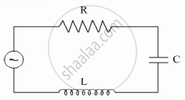
(i) Find the value of the phase difference between the current and the voltage in the series LCR circuit shown below. Which one leads in phase : current or voltage ?
(ii) Without making any other change, find the value of the additional capacitor C1, to be connected in parallel with the capacitor C, in order to make the power factor of the circuit unity.

The figure shows a series LCR circuit with L = 10.0 H, C = 40 μF, R = 60 Ω connected to a variable frequency 240 V source, calculate
(i) the angular frequency of the source which drives the circuit at resonance,
(ii) the current at the resonating frequency,
(iii) the rms potential drop across the inductor at resonance.
The time constant of an LR circuit is 40 ms. The circuit is connected at t = 0 and the steady-state current is found to be 2.0 A. Find the current at (a) t = 10 ms (b) t = 20 ms, (c) t = 100 ms and (d) t = 1 s.
A solenoid having inductance 4.0 H and resistance 10 Ω is connected to a 4.0 V battery at t = 0. Find (a) the time constant, (b) the time elapsed before the current reaches 0.63 of its steady-state value, (c) the power delivered by the battery at this instant and (d) the power dissipated in Joule heating at this instant.
(i) An a.c. source of emf ε = 200 sin omegat is connected to a resistor of 50 Ω . calculate :
(1) Average current (`"I"_("avg")`)
(2) Root mean square (rms) value of emf
(ii) State any two characteristics of resonance in an LCR series circuit.
Three students, X, Y and Z performed an experiment for studying the variation of ac with frequency in a series LCR circuit and obtained the graphs as shown below. They all used
- an AC source of the same emf and
- inductance of the same value.

- Who used minimum resistance?
- In which case will the quality Q factor be maximum?
- What did the students conclude about the nature of impedance at resonant frequency (f0)?
- An ideal capacitor is connected across 220 V, 50 Hz, and 220 V, 100 Hz supplies. Find the ratio of current flowing through it in the two cases.
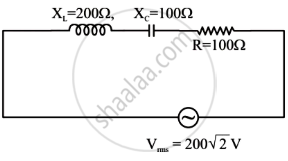
In the given circuit, rms value of current (Irms) through the resistor R is:
Out of the following which one is NOT the characteristic of LCR series resonant circuit?
