Advertisements
Advertisements
प्रश्न
A source of ac voltage v = v0 sin ωt, is connected across a pure inductor of inductance L. Derive the expressions for the instantaneous current in the circuit. Show that average power dissipated in the circuit is zero.
Advertisements
उत्तर
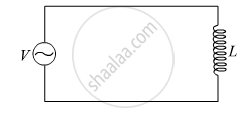
Using Kirchhoff’s loop rule in the above circuit,
\[V - L\frac{dI}{dt} = 0\]
\[\text { where, I is the instantaneous current flowing in the circuit }\]
\[ \Rightarrow L\frac{dI}{dt} = V_o \sin\omega t\]
\[ \Rightarrow \int dI = \frac{V_o}{L}\int\sin\omega tdt\]
\[ \Rightarrow I = \frac{V_o}{L}[ -\frac{\cos\omega t}{\omega}]\]
\[ \Rightarrow I = - \frac{V_o}{\omega L}\cos\omega t\]
\[ \Rightarrow I = \frac{V_o}{X_L}\sin(\omega t - \frac{\pi}{2})\]
\[\text { where, }X_L = \omega L = \text { inductance reactance }\]
\[ \therefore I = I_o \sin(\omega t - \frac{\pi}{2})\]
\[\text { where,} I_o = \frac{V_o}{X_L} =\text { peak value of ac}\]
\[\text { Now instantaneous power supplied by the source is } \]
\[P = VI = V_o I_o \sin\omega t \sin(\omega t - \frac{\pi}{2})\]
\[\text { Now the average power } ( P_{avg} ) \text { supplied over a complete cycle} ( 0 to 2\pi) \text { is }\]
\[ P_{avg} = \int_o^{2\pi} P = \int_o^{2\pi} V_o I_o \sin\theta \sin(\theta - \frac{\pi}{2})d\theta [\text { where } \theta = \omega t]\]
\[\text { Now over a complete cycle } \int_o^{2\pi} \sin\theta\sin(\theta - \frac{\pi}{2})d\theta = 0\]
\[\text { Therefore, }P_{avg} = \int_o^{2\pi} V_o I_o \text { sin }\theta\sin(\theta - \frac{\pi}{2})d\theta = 0\]
\[ P_{avg} = 0\]
Hence, the average power dissipated in the circuit is zero.
APPEARS IN
संबंधित प्रश्न
In a series LCR circuit, VL = VC ≠ VR. What is the value of power factor?
A coil having an inductance L and a resistance R is connected to a battery of emf ε. Find the time taken for the magnetic energy stored in the circuit to change from one fourth of the steady-state value to half of the steady-state value.
To reduce the resonant frequency in an LCR series circuit with a generator ______.
A coil of 0.01 henry inductance and 1 ohm resistance is connected to 200 volt, 50 Hz ac supply. Find the impedance of the circuit and time lag between max. alternating voltage and current.
A series LCR circuit containing a resistance of 120 Ω has angular resonance frequency 4 × 10⁵ rad s-1. At resonance the voltage across resistance and inductance are 60 V and 40 V respectively. At what frequency the current in the circuit lags the voltage by 45°. Give answer in ______ × 105 rad s-1.
A series LCR circuit (L = 10 H, C = 10 µF, R = 50 Ω) is connected to V = 200 sin (100t). If ν0 is the resonant frequency and ν is the source frequency, then ______.
To reduce the resonant frequency in an L-C-R series circuit with a generator ______.
A 20Ω resistance, 10 mH inductance coil and 15µF capacitor are joined in series. When a suitable frequency alternating current source is joined to this combination, the circuit resonates. If the resistance is made \[\frac {1}{3}\] rd, the resonant frequency ______.
When a capacitor is connected in series LR circuit, the alternating current flowing in the circuit ______
