Advertisements
Advertisements
Question
To reduce the resonant frequency in an LCR series circuit with a generator ______.
Options
the generator frequency should be reduced.
another capacitor should be added in parallel to the first.
the iron core of the inductor should be removed.
dielectric in the capacitor should be removed.
Advertisements
Solution
To reduce the resonant frequency in an LCR series circuit with a generator another capacitor should be added in parallel to the first.
Explanation:
At response XL = XC ⇒ ω0L = `1/(ω_0C)`
⇒ ω0 = `1/sqrt(LC) "rad"/sec`
⇒ v0 = `1/(2pisqrt(LC)) Hz`
Resonant frequency in an L-C-R circuit is given by
`v_0 = 1/(2pisqrt(LC))`
If L or C increases, the resonant frequency will reduce.
To increase capacitance, we must connect another capacitor parallel to the first.
APPEARS IN
RELATED QUESTIONS
A source of ac voltage v = v0 sin ωt, is connected across a pure inductor of inductance L. Derive the expressions for the instantaneous current in the circuit. Show that average power dissipated in the circuit is zero.
An L-R circuit has L = 1.0 H and R = 20 Ω. It is connected across an emf of 2.0 V at t = 0. Find di/dt at (a) t = 100 ms, (b) t = 200 ms and (c) t = 1.0 s.
A solenoid having inductance 4.0 H and resistance 10 Ω is connected to a 4.0 V battery at t = 0. Find (a) the time constant, (b) the time elapsed before the current reaches 0.63 of its steady-state value, (c) the power delivered by the battery at this instant and (d) the power dissipated in Joule heating at this instant.
A constant current exists in an inductor-coil connected to a battery. The coil is short-circuited and the battery is removed. Show that the charge flown through the coil after the short-circuiting is the same as that which flows in one time constant before the short-circuiting.
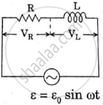
An ac circuit as shown in the figure has an inductor of inductance L and a resistor or resistance R connected in series. Using the phasor diagram, explain why the voltage in the circuit will lead the current in phase.
What will be the potential difference in the circuit when direct current is passed through the circuit?
A series LCR circuit with R = 20 Ω, L = 1.5 H and C = 35 µF is connected to a variable-frequency 200 V ac supply. When the frequency of the supply equals the natural frequency of the circuit, what is the average power transferred to the circuit in one complete cycle?
Figure shows a series LCR circuit connected to a variable frequency 230 V source. L = 5.0 H, C = 80 µF, R = 40 Ω.
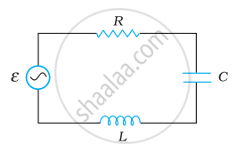
- Determine the source frequency which drives the circuit in resonance.
- Obtain the impedance of the circuit and the amplitude of current at the resonating frequency.
- Determine the rms potential drops across the three elements of the circuit. Show that the potential drop across the LC combination is zero at the resonating frequency.
Keeping the source frequency equal to the resonating frequency of the series LCR circuit, if the three elements, L, C and R are arranged in parallel, show that the total current in the parallel LCR circuit is minimum at this frequency. Obtain the current rms value in each branch of the circuit for the elements and source specified for this frequency.
Obtain the resonant frequency and Q-factor of a series LCR circuit with L = 3.0 H, C = 27 µF, and R = 7.4 Ω. It is desired to improve the sharpness of the resonance of the circuit by reducing its ‘full width at half maximum’ by a factor of 2. Suggest a suitable way.
In an L.C.R. series a.c. circuit, the current ______.
In an LCR series a.c. circuit, the voltage across each of the components, L, C and R is 50V. The voltage across the LC combination will be ______.
A coil of 40 henry inductance is connected in series with a resistance of 8 ohm and the combination is joined to the terminals of a 2 volt battery. The time constant of the circuit is ______.
Consider the LCR circuit shown in figure. Find the net current i and the phase of i. Show that i = v/Z`. Find the impedance Z for this circuit.

Which of the following statements about a series LCR circuit connected to an ac source is correct?
Select the most appropriate option with regard to resonance in a series LCR circuit.
Draw a labelled graph showing variation of impedance (Z) of a series LCR circuit Vs frequency (f) of the ac supply. Mark the resonant frequency as f0·
In a series LCR circuit, the inductance L is 10 mH, capacitance C is 1 µF and resistance R is 100Ω. The frequency at which resonance occurs is ______.
What constitutes a series LCR circuit?
Which expression gives the sinusoidally varying voltage applied by the AC source?
