Advertisements
Advertisements
Question
A coil of 0.01 henry inductance and 1 ohm resistance is connected to 200 volt, 50 Hz ac supply. Find the impedance of the circuit and time lag between max. alternating voltage and current.
Advertisements
Solution
R = 1 Ω, L = 0.01 H, V = 200 V, v = 50 Hz.
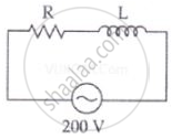
Impedance of the circuit
`Z = sqrt(R^2 + X_L^2) = sqrt(R^2 + (2pivL)^2)`
= `sqrt((1)^2 + (2 xx 3.14 xx 50 xx 0.1)^2)`
= `sqrt(1 + 9.86) = sqrt(10.86)`
= 3.3 Ω
∴ For phase angle, tan `phi = Z/R`
`tan phi = X_L/R = (2pivL)/R = (2 xx 3.14 xx 50 xx 0.01)/1`
`tan phi` = 3.14
`phi` = tan–1 3.14 = 72°
Phase difference
`phi = (72 xx pi)/180^circ` rad
`phi` = 1.20 radian
Time lag between alternating voltage and current
| `phi` = ωt |
`t = phi/ω = (72 xx pi)/(180 xx 2 xx pi xx 50) = 1/250` sec
APPEARS IN
RELATED QUESTIONS
In a series LCR circuit connected to an a.c. source of voltage v = vmsinωt, use phasor diagram to derive an expression for the current in the circuit. Hence, obtain the expression for the power dissipated in the circuit. Show that power dissipated at resonance is maximum
Show that in an a.c. circuit containing a pure inductor, the voltage is ahead of current by π/2 in phase ?
A coil of resistance 40 Ω is connected across a 4.0 V battery. 0.10 s after the battery is connected, the current in the coil is 63 mA. Find the inductance of the coil.
A coil having an inductance L and a resistance R is connected to a battery of emf ε. Find the time taken for the magnetic energy stored in the circuit to change from one fourth of the steady-state value to half of the steady-state value.
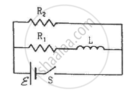
Consider the circuit shown in figure. (a) Find the current through the battery a long time after the switch S is closed. (b) Suppose the switch is again opened at t = 0. What is the time constant of the discharging circuit? (c) Find the current through the inductor after one time constant.
Keeping the source frequency equal to the resonating frequency of the series LCR circuit, if the three elements, L, C and R are arranged in parallel, show that the total current in the parallel LCR circuit is minimum at this frequency. Obtain the current rms value in each branch of the circuit for the elements and source specified for this frequency.
In a series LCR circuit supplied with AC, ______.
If an LCR series circuit is connected to an ac source, then at resonance the voltage across ______.
In an LCR series a.c. circuit, the voltage across each of the components, L, C and R is 50V. The voltage across the LC combination will be ______.
To reduce the resonant frequency in an LCR series circuit with a generator ______.
Which of the following combinations should be selected for better tuning of an LCR circuit used for communication?
As the frequency of an ac circuit increases, the current first increases and then decreases. What combination of circuit elements is most likely to comprise the circuit?
- Inductor and capacitor.
- Resistor and inductor.
- Resistor and capacitor.
- Resistor, inductor and capacitor.
For an LCR circuit driven at frequency ω, the equation reads
`L (di)/(dt) + Ri + q/C = v_i = v_m` sin ωt
- Multiply the equation by i and simplify where possible.
- Interpret each term physically.
- Cast the equation in the form of a conservation of energy statement.
- Integrate the equation over one cycle to find that the phase difference between v and i must be acute.
A series LCR circuit driven by 300 V at a frequency of 50 Hz contains a resistance R = 3 kΩ, an inductor of inductive reactance XL = 250 πΩ, and an unknown capacitor. The value of capacitance to maximize the average power should be ______.
An alternating voltage of 220 V is applied across a device X. A current of 0.22 A flows in the circuit and it lags behind the applied voltage in phase by π/2 radian. When the same voltage is applied across another device Y, the current in the circuit remains the same and it is in phase with the applied voltage.
- Name the devices X and Y and,
- Calculate the current flowing in the circuit when the same voltage is applied across the series combination of X and Y.
Select the most appropriate option with regard to resonance in a series LCR circuit.
The net impedance of circuit (as shown in figure) will be ______.
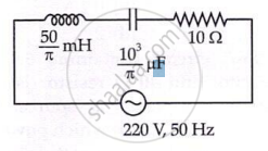
What constitutes a series LCR circuit?
What is true of the current through the resistor, inductor, and capacitor at every instant?
