Advertisements
Advertisements
प्रश्न
A coil of 0.01 henry inductance and 1 ohm resistance is connected to 200 volt, 50 Hz ac supply. Find the impedance of the circuit and time lag between max. alternating voltage and current.
Advertisements
उत्तर
R = 1 Ω, L = 0.01 H, V = 200 V, v = 50 Hz.
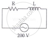
Impedance of the circuit
`Z = sqrt(R^2 + X_L^2) = sqrt(R^2 + (2pivL)^2)`
= `sqrt((1)^2 + (2 xx 3.14 xx 50 xx 0.1)^2)`
= `sqrt(1 + 9.86) = sqrt(10.86)`
= 3.3 Ω
∴ For phase angle, tan `phi = Z/R`
`tan phi = X_L/R = (2pivL)/R = (2 xx 3.14 xx 50 xx 0.01)/1`
`tan phi` = 3.14
`phi` = tan–1 3.14 = 72°
Phase difference
`phi = (72 xx pi)/180^circ` rad
`phi` = 1.20 radian
Time lag between alternating voltage and current
| `phi` = ωt |
`t = phi/ω = (72 xx pi)/(180 xx 2 xx pi xx 50) = 1/250` sec
APPEARS IN
संबंधित प्रश्न
In a series LCR circuit, VL = VC ≠ VR. What is the value of power factor?
A voltage V = V0 sin ωt is applied to a series LCR circuit. Derive the expression for the average power dissipated over a cycle. Under what condition (i) no power is dissipated even though the current flows through the circuit, (ii) maximum power is dissipated in the circuit?
A source of ac voltage v = v0 sin ωt, is connected across a pure inductor of inductance L. Derive the expressions for the instantaneous current in the circuit. Show that average power dissipated in the circuit is zero.
A series LCR circuit is connected to an ac source. Using the phasor diagram, derive the expression for the impedance of the circuit. Plot a graph to show the variation of current with frequency of the source, explaining the nature of its variation.
A series LCR circuit is connected to a source having voltage v = vm sin ωt. Derive the expression for the instantaneous current I and its phase relationship to the applied voltage.
Obtain the condition for resonance to occur. Define ‘power factor’. State the conditions under which it is (i) maximum and (ii) minimum.
Derive an expression for the average power consumed in a series LCR circuit connected to a.c. source in which the phase difference between the voltage and the current in the circuit is Φ.
An inductor of inductance 2.00 H is joined in series with a resistor of resistance 200 Ω and a battery of emf 2.00 V. At t = 10 ms, find (a) the current in the circuit, (b) the power delivered by the battery, (c) the power dissipated in heating the resistor and (d) the rate at which energy is being stored in magnetic field.
Two coils A and B have inductances 1.0 H and 2.0 H respectively. The resistance of each coil is 10 Ω. Each coil is connected to an ideal battery of emf 2.0 V at t = 0. Let iA and iBbe the currents in the two circuit at time t. Find the ratio iA / iB at (a) t = 100 ms, (b) t = 200 ms and (c) t = 1 s.
Draw a labelled graph showing a variation of impedance of a series LCR circuit with frequency of the a.c. supply.
A series LCR circuit with R = 20 Ω, L = 1.5 H and C = 35 µF is connected to a variable-frequency 200 V ac supply. When the frequency of the supply equals the natural frequency of the circuit, what is the average power transferred to the circuit in one complete cycle?
Obtain the resonant frequency and Q-factor of a series LCR circuit with L = 3.0 H, C = 27 µF, and R = 7.4 Ω. It is desired to improve the sharpness of the resonance of the circuit by reducing its ‘full width at half maximum’ by a factor of 2. Suggest a suitable way.
In a series LCR circuit supplied with AC, ______.
In an L.C.R. series a.c. circuit, the current ______.
The resonant frequency of a RF oscillator is 1 MHz and its bandwidth is 10 kHz. The quality factor will be :
Define Impedance.
A series RL circuit with R = 10 Ω and L = `(100/pi)` mH is connected to an ac source of voltage V = 141 sin (100 πt), where V is in volts and t is in seconds. Calculate
- the impedance of the circuit
- phase angle, and
- the voltage drop across the inductor.
Select the most appropriate option with regard to resonance in a series LCR circuit.
What constitutes a series LCR circuit?
Which circuit equation results from applying Kirchhoff's Voltage Law around the series LCR loop?
