Advertisements
Advertisements
Question
Two coils A and B have inductances 1.0 H and 2.0 H respectively. The resistance of each coil is 10 Ω. Each coil is connected to an ideal battery of emf 2.0 V at t = 0. Let iA and iBbe the currents in the two circuit at time t. Find the ratio iA / iB at (a) t = 100 ms, (b) t = 200 ms and (c) t = 1 s.
Advertisements
Solution
Given:-
Inductance of the coil A, LA = 1.0 H
Inductance of the coil B, LB = 2.0 H
Resistance in each coil, R = 10 Ω
The current in the LR circuit after t seconds after connecting the battery is given by
i = i0 (1 − e−t/τ)
Here,
i0 = Steady state current
τ = Time constant = `L/R`
(a) At t = 0.1 s, time constants of the coils A and B are τA and τB, respectively.
Now,
\[\tau_A = \frac{1}{10} = 0 . 1 s\]
\[ \tau_B = \frac{2}{10} = 0 . 2 s\]
Currents in the coils can be calculated as follows:-
\[i_A = i_0 (1 - e^{- t/\tau} ), \]
\[ = \frac{2}{10}\left( 1 - e^\frac{0 . 1 \times 10}{1} \right) = 0 . 2 (1 - e^{- 1} )\]
\[ = 0 . 126424111\]
\[ i_B = i_0 (1 - e^{- t/\tau} )\]
\[ = \frac{2}{10}(1 - e^{0 . 1 \times 10/2} )\]
\[ = 0 . 2 (1 - e^{- 1/2} ) = 0 . 078693\]
\[\therefore \frac{i_A}{i_B} = \frac{0 . 126411}{0 . 78693} = 1 . 6\]
(b) At t = 200 ms = 0.2 s,
iA = 0.2 (1 − e−0.2 × 10.1)
iA = 0.2 × 0.864664716
iA = 0.1729329943
iB = 0.2 (1 − e−0.2 × 10.2)
iB = 0.2 × 0.632120 = 0.126424111
\[\therefore \frac{i_A}{i_B} = \frac{0 . 172932343}{0 . 126424111} = 1 . 36 = 1 . 4\]
(c) At time t = 1 s,
iA = 0.2 (1 − e−1 × 10.1)
= 0.2 − 0.9999549
= 0.19999092
iB = 0.2 (1 − e−1 × 10.2)
= 0.2 × 0.99326 = 0.19865241
\[\therefore \frac{i_A}{i_B} = \frac{0 . 19999092}{0 . 19999092} \approx 1 . 0\]
APPEARS IN
RELATED QUESTIONS
In a series LCR circuit, VL = VC ≠ VR. What is the value of power factor?
A voltage V = V0 sin ωt is applied to a series LCR circuit. Derive the expression for the average power dissipated over a cycle. Under what condition (i) no power is dissipated even though the current flows through the circuit, (ii) maximum power is dissipated in the circuit?
(i) Find the value of the phase difference between the current and the voltage in the series LCR circuit shown below. Which one leads in phase : current or voltage ?
(ii) Without making any other change, find the value of the additional capacitor C1, to be connected in parallel with the capacitor C, in order to make the power factor of the circuit unity.

A coil of resistance 40 Ω is connected across a 4.0 V battery. 0.10 s after the battery is connected, the current in the coil is 63 mA. Find the inductance of the coil.
An L-R circuit has L = 1.0 H and R = 20 Ω. It is connected across an emf of 2.0 V at t = 0. Find di/dt at (a) t = 100 ms, (b) t = 200 ms and (c) t = 1.0 s.
An inductor-coil of inductance 17 mH is constructed from a copper wire of length 100 m and cross-sectional area 1 mm2. Calculate the time constant of the circuit if this inductor is joined across an ideal battery. The resistivity of copper = 1.7 × 10⁻⁸ Ω-m.
An LR circuit having a time constant of 50 ms is connected with an ideal battery of emf ε. find the time elapsed before (a) the current reaches half its maximum value, (b) the power dissipated in heat reaches half its maximum value and (c) the magnetic field energy stored in the circuit reaches half its maximum value.
In a series, LCR circuit, obtain an expression for the resonant frequency.
Choose the correct answer from given options
The phase difference between the current and the voltage in series LCR circuit at resonance is
In a series LCR circuit supplied with AC, ______.
In an L.C.R. series a.c. circuit, the current ______.
If an LCR series circuit is connected to an ac source, then at resonance the voltage across ______.
A series LCR circuit contains inductance 5 mH, capacitance 2µF and resistance ion. If a frequency A.C. source is varied, what is the frequency at which maximum power is dissipated?
In series LCR AC-circuit, the phase angle between current and voltage is
Which of the following components of an LCR circuit, with a.c. supply, dissipates energy?
A series LCR circuit containing a 5.0 H inductor, 80 µF capacitors, and 40 Ω resistor is connected to a 230 V variable frequency ac source. The angular frequencies of the source at which power is transferred to the circuit are half the power at the resonant angular frequency are likely to be ______.
If the rms current in a 50 Hz ac circuit is 5 A, the value of the current 1/300 seconds after its value becomes zero is ______.
Which of the following combinations should be selected for better tuning of an LCR circuit used for communication?
Draw a labelled graph showing variation of impedance (Z) of a series LCR circuit Vs frequency (f) of the ac supply. Mark the resonant frequency as f0·
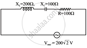
In the given circuit, rms value of current (Irms) through the resistor R is: