Advertisements
Advertisements
प्रश्न
Which of the following combinations should be selected for better tuning of an LCR circuit used for communication?
विकल्प
R = 20 Ω, L = 1.5 H, C = 35µF.
R = 25 Ω, L = 2.5 H, C = 45µF.
R = 15 Ω, L = 3.5 H, C = 30µF.
R = 25 Ω, L = 1.5 H, C = 45µF.
Advertisements
उत्तर
R = 15 Ω, L = 3.5 H, C = 30µF.
Explanation:
Quality factor (Q-factor) of the series resonant circuit:
(i) The characteristic of a series resonant circuit is determined by the quality factor (Q-factor) of the circuit.
(ii) It defines sharpness if i - v curve at resonance when Q-factor is large, the sharpness of resonance curve is more and vice-versa.
(iii) Q-factor is also defined as follows:
Q-factor = `2pi xx "Max energy stored"/"Energy dissipation"`
= `(2pi)/T xx "Max energy stored"/"Mean power dissipated"`
= `"Resonant frequency"/"Bandwidth" = ω_0/(Δω)`
(iv) Q-factor = `V_L/V_R` or `V_C/V_R = (ω_0L)/R` or `1/(ω_0CR)`
⇒ Q-factor = `1/R sqrt(L/C)`
For better tuning of an L-C-R circuit used for communication, quality factor of the circuit must be as high as possible.

We know quality factor should be high for better tuning.
Quality factor (Q) of an L-C-R circuit is `Q = 1/R sqrt(L/C)`
Where R is the resistance, L is the inductance and C is the capacitance of the circuit.
For high Q factor R should be low, L should be high and C should be low.
Important point: Be careful while writing formula for quality factor, this formula we used in this case is only for series L-C-R circuit.
APPEARS IN
संबंधित प्रश्न
In a series LCR circuit, VL = VC ≠ VR. What is the value of power factor?
A series LCR circuit is connected across an a.c. source of variable angular frequency 'ω'. Plot a graph showing variation of current 'i' as a function of 'ω' for two resistances R1 and R2 (R1 > R2).
Answer the following questions using this graph :
(a) In which case is the resonance sharper and why?
(b) In which case in the power dissipation more and why?
Derive an expression for the average power consumed in a series LCR circuit connected to a.c. source in which the phase difference between the voltage and the current in the circuit is Φ.
The time constant of an LR circuit is 40 ms. The circuit is connected at t = 0 and the steady-state current is found to be 2.0 A. Find the current at (a) t = 10 ms (b) t = 20 ms, (c) t = 100 ms and (d) t = 1 s.
An LR circuit with emf ε is connected at t = 0. (a) Find the charge Q which flows through the battery during 0 to t. (b) Calculate the work done by the battery during this period. (c) Find the heat developed during this period. (d) Find the magnetic field energy stored in the circuit at time t. (e) Verify that the results in the three parts above are consistent with energy conservation.
Derive an expression for the average power dissipated in a series LCR circuit.
Obtain the resonant frequency and Q-factor of a series LCR circuit with L = 3.0 H, C = 27 µF, and R = 7.4 Ω. It is desired to improve the sharpness of the resonance of the circuit by reducing its ‘full width at half maximum’ by a factor of 2. Suggest a suitable way.
In an L.C.R. series a.c. circuit, the current ______.
In an LCR series a.c. circuit, the voltage across each of the components, L, C and R is 50V. The voltage across the LC combination will be ______.
Assertion: When the frequency of the AC source in an LCR circuit equals the resonant frequency, the reactance of the circuit is zero, and so there is no current through the inductor or the capacitor.
Reason: The net current in the inductor and capacitor is zero.
A coil of 40 henry inductance is connected in series with a resistance of 8 ohm and the combination is joined to the terminals of a 2 volt battery. The time constant of the circuit is ______.
To reduce the resonant frequency in an LCR series circuit with a generator
In series LCR AC-circuit, the phase angle between current and voltage is
A series LCR circuit containing a 5.0 H inductor, 80 µF capacitors, and 40 Ω resistor is connected to a 230 V variable frequency ac source. The angular frequencies of the source at which power is transferred to the circuit are half the power at the resonant angular frequency are likely to be ______.
Consider the LCR circuit shown in figure. Find the net current i and the phase of i. Show that i = v/Z`. Find the impedance Z for this circuit.

For an LCR circuit driven at frequency ω, the equation reads
`L (di)/(dt) + Ri + q/C = v_i = v_m` sin ωt
- Multiply the equation by i and simplify where possible.
- Interpret each term physically.
- Cast the equation in the form of a conservation of energy statement.
- Integrate the equation over one cycle to find that the phase difference between v and i must be acute.
A series LCR circuit containing a resistance of 120 Ω has angular resonance frequency 4 × 10⁵ rad s-1. At resonance the voltage across resistance and inductance are 60 V and 40 V respectively. At what frequency the current in the circuit lags the voltage by 45°. Give answer in ______ × 105 rad s-1.
A resistance of 200Ω and an inductor of \[\frac {1}{2π}\]Н are connected in series to a.c. voltage of 40 V and 100 Hz frequency. The phase angle between the voltage and current is ______.
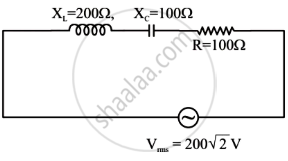
In the given circuit, rms value of current (Irms) through the resistor R is: