Advertisements
Advertisements
प्रश्न
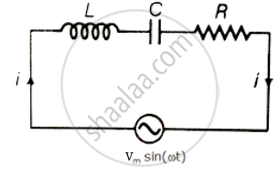
For an LCR circuit driven at frequency ω, the equation reads
`L (di)/(dt) + Ri + q/C = v_i = v_m` sin ωt
- Multiply the equation by i and simplify where possible.
- Interpret each term physically.
- Cast the equation in the form of a conservation of energy statement.
- Integrate the equation over one cycle to find that the phase difference between v and i must be acute.
Advertisements
उत्तर
Consider L-C-R series circuit with AC supply
V = Vm sin ωt
Applying voltage Kirchhoff's law over the circuit
∴ VL + VC + VR = Vm sin ωt
L = `(di)/(dt) + Ri + q/c` = Vi = Vm sin ωt
Multiply the above equation by i on both the sides.
L = `(di)/(dt) + Ri + q/c` = Vi = Vm sin ωt
Multiply the above equation by `1/2` on both sides
`1/2 Li (di)/(dt) + i q/(2C) + (i^2R)/2 = 1/2` Vmi sin ωt `(∵ i = (dq)/(dt))`
`(d(1/2 Li^2))/(dt) + 1/(2C) (dq^2)/(dt) + (i^2R)/2 = 1/2` Vmi sin ωt .....(I)
(i) `(d(1/2 li^2))/(dt)` Represents the rate of change of potential energy in inductance L.
(ii) `d/(dt) q^2/(2C)` represents energy stored in dt time in the capacitor.
(iii) i2R represents joules heating loss.
(iv) `1/2 V_m i` sin ωt is the rate at which driving force pours in energy. It goes into ohmic loss and increase of stored energy in capacitor and inductor.
Vi = rate at which driving force pours in energy. It goes into (i) ohmic loss and (ii) increase of stored energy.
Hence equation (ii) is in the form of conservation of energy statement. Integrating both sides of equation. (ii) with respect to time over one full cycle (0 → T) we may write
`int_0^T d/(dt) (1/2 Li^2 + q^2/(2C)) dt + int_0^T Ri^2 dt = int_0^T Vi dt`
⇒ 0 + (+ ve) = `int_0^T Vi dt`
⇒ `int_0^T Vi dt > 0` if phase difference between V and i is a constant and acute angle.
APPEARS IN
संबंधित प्रश्न
Define 'quality factor' of resonance in a series LCR circuit. What is its SI unit?
A series LCR circuit is connected to a source having voltage v = vm sin ωt. Derive the expression for the instantaneous current I and its phase relationship to the applied voltage.
Obtain the condition for resonance to occur. Define ‘power factor’. State the conditions under which it is (i) maximum and (ii) minimum.
An LR circuit contains an inductor of 500 mH, a resistor of 25.0 Ω and an emf of 5.00 V in series. Find the potential difference across the resistor at t = (a) 20.0 ms, (b) 100 ms and (c) 1.00 s.
An inductor-coil of inductance 17 mH is constructed from a copper wire of length 100 m and cross-sectional area 1 mm2. Calculate the time constant of the circuit if this inductor is joined across an ideal battery. The resistivity of copper = 1.7 × 10⁻⁸ Ω-m.
Answer the following question.
What is the phase difference between the voltages across the inductor and the capacitor at resonance in the LCR circuit?
Use the expression for Lorentz force acting on the charge carriers of a conductor to obtain the expression for the induced emf across the conductor of length l moving with velocity v through a magnetic field B acting perpendicular to its length.
Using the phasor diagram, derive the expression for the current flowing in an ideal inductor connected to an a.c. source of voltage, v= vo sin ωt. Hence plot graphs showing the variation of (i) applied voltage and (ii) the current as a function of ωt.
Derive an expression for the average power dissipated in a series LCR circuit.
Figure shows a series LCR circuit connected to a variable frequency 230 V source. L = 5.0 H, C = 80 µF, R = 40 Ω.

- Determine the source frequency which drives the circuit in resonance.
- Obtain the impedance of the circuit and the amplitude of current at the resonating frequency.
- Determine the rms potential drops across the three elements of the circuit. Show that the potential drop across the LC combination is zero at the resonating frequency.
In an L.C.R. series a.c. circuit, the current ______.
Assertion: When the frequency of the AC source in an LCR circuit equals the resonant frequency, the reactance of the circuit is zero, and so there is no current through the inductor or the capacitor.
Reason: The net current in the inductor and capacitor is zero.
At resonance frequency the impedance in series LCR circuit is ______.
A coil of 0.01 henry inductance and 1 ohm resistance is connected to 200 volt, 50 Hz ac supply. Find the impedance of the circuit and time lag between max. alternating voltage and current.
Which of the following statements about a series LCR circuit connected to an ac source is correct?
When an alternating voltage of 220V is applied across device X, a current of 0.25A flows which lags behind the applied voltage in phase by π/2 radian. If the same voltage is applied across another device Y, the same current flows but now it is in phase with the applied voltage.
- Name the devices X and Y.
- Calculate the current flowing in the circuit when the same voltage is applied across the series combination of X and Y.
In a series LCR circuit, the inductance L is 10 mH, capacitance C is 1 µF and resistance R is 100Ω. The frequency at which resonance occurs is ______.
To reduce the resonant frequency in an L-C-R series circuit with a generator ______.
When a capacitor is connected in series LR circuit, the alternating current flowing in the circuit ______
Out of the following which one is NOT the characteristic of LCR series resonant circuit?
