Advertisements
Advertisements
प्रश्न
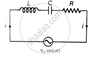
For an LCR circuit driven at frequency ω, the equation reads
`L (di)/(dt) + Ri + q/C = v_i = v_m` sin ωt
- Multiply the equation by i and simplify where possible.
- Interpret each term physically.
- Cast the equation in the form of a conservation of energy statement.
- Integrate the equation over one cycle to find that the phase difference between v and i must be acute.
Advertisements
उत्तर
Consider L-C-R series circuit with AC supply
V = Vm sin ωt
Applying voltage Kirchhoff's law over the circuit
∴ VL + VC + VR = Vm sin ωt
L = `(di)/(dt) + Ri + q/c` = Vi = Vm sin ωt
Multiply the above equation by i on both the sides.
L = `(di)/(dt) + Ri + q/c` = Vi = Vm sin ωt
Multiply the above equation by `1/2` on both sides
`1/2 Li (di)/(dt) + i q/(2C) + (i^2R)/2 = 1/2` Vmi sin ωt `(∵ i = (dq)/(dt))`
`(d(1/2 Li^2))/(dt) + 1/(2C) (dq^2)/(dt) + (i^2R)/2 = 1/2` Vmi sin ωt .....(I)
(i) `(d(1/2 li^2))/(dt)` Represents the rate of change of potential energy in inductance L.
(ii) `d/(dt) q^2/(2C)` represents energy stored in dt time in the capacitor.
(iii) i2R represents joules heating loss.
(iv) `1/2 V_m i` sin ωt is the rate at which driving force pours in energy. It goes into ohmic loss and increase of stored energy in capacitor and inductor.
Vi = rate at which driving force pours in energy. It goes into (i) ohmic loss and (ii) increase of stored energy.
Hence equation (ii) is in the form of conservation of energy statement. Integrating both sides of equation. (ii) with respect to time over one full cycle (0 → T) we may write
`int_0^T d/(dt) (1/2 Li^2 + q^2/(2C)) dt + int_0^T Ri^2 dt = int_0^T Vi dt`
⇒ 0 + (+ ve) = `int_0^T Vi dt`
⇒ `int_0^T Vi dt > 0` if phase difference between V and i is a constant and acute angle.
APPEARS IN
संबंधित प्रश्न
In a series LCR circuit, obtain the condition under which watt-less current flows in the circuit ?
An inductor-coil of resistance 10 Ω and inductance 120 mH is connected across a battery of emf 6 V and internal resistance 2 Ω. Find the charge which flows through the inductor in (a) 10 ms, (b) 20 ms and (c) 100 ms after the connections are made.
The current in a discharging LR circuit without the battery drops from 2.0 A to 1.0 A in 0.10 s. (a) Find the time constant of the circuit. (b) If the inductance of the circuit 4.0 H, what is its resistance?
(i) An a.c. source of emf ε = 200 sin omegat is connected to a resistor of 50 Ω . calculate :
(1) Average current (`"I"_("avg")`)
(2) Root mean square (rms) value of emf
(ii) State any two characteristics of resonance in an LCR series circuit.
What will be the potential difference in the circuit when direct current is passed through the circuit?
Answer the following question.
What is the phase difference between the voltages across the inductor and the capacitor at resonance in the LCR circuit?
Answer the following question.
Draw the diagram of a device that is used to decrease high ac voltage into a low ac voltage and state its working principle. Write four sources of energy loss in this device.
Figure shows a series LCR circuit connected to a variable frequency 230 V source. L = 5.0 H, C = 80 µF, R = 40 Ω.

- Determine the source frequency which drives the circuit in resonance.
- Obtain the impedance of the circuit and the amplitude of current at the resonating frequency.
- Determine the rms potential drops across the three elements of the circuit. Show that the potential drop across the LC combination is zero at the resonating frequency.
In series combination of R, L and C with an A.C. source at resonance, if R = 20 ohm, then impedence Z of the combination is ______.
A coil of 40 henry inductance is connected in series with a resistance of 8 ohm and the combination is joined to the terminals of a 2 volt battery. The time constant of the circuit is ______.
At resonance frequency the impedance in series LCR circuit is ______.
In an LCR circuit having L = 8 henery. C = 0.5 µF and R = 100 ohm in series, the resonance frequency in radian/sec is
Which of the following components of an LCR circuit, with a.c. supply, dissipates energy?
As the frequency of an ac circuit increases, the current first increases and then decreases. What combination of circuit elements is most likely to comprise the circuit?
- Inductor and capacitor.
- Resistor and inductor.
- Resistor and capacitor.
- Resistor, inductor and capacitor.
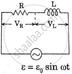
Consider the LCR circuit shown in figure. Find the net current i and the phase of i. Show that i = v/Z`. Find the impedance Z for this circuit.

Define Impedance.
A series LCR circuit driven by 300 V at a frequency of 50 Hz contains a resistance R = 3 kΩ, an inductor of inductive reactance XL = 250 πΩ, and an unknown capacitor. The value of capacitance to maximize the average power should be ______.
To reduce the resonant frequency in an L-C-R series circuit with a generator ______.
When a capacitor is connected in series LR circuit, the alternating current flowing in the circuit ______
