Advertisements
Advertisements
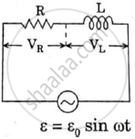
प्रश्न
Obtain the resonant frequency and Q-factor of a series LCR circuit with L = 3.0 H, C = 27 µF, and R = 7.4 Ω. It is desired to improve the sharpness of the resonance of the circuit by reducing its ‘full width at half maximum’ by a factor of 2. Suggest a suitable way.
Advertisements
उत्तर
Inductance, L = 3.0 H
Capacitance, C = 27 μF = 27 × 10−6 F
Resistance, R = 7.4 Ω
At resonance, the angular frequency of the source for the given LCR series circuit is given as:
ωr = `1/sqrt"LC"`
= `1/sqrt(3 xx 27 xx 10^-6)`
= `10^3/9`
= 111.11 rad s−1
Q-factor of the series:
Q = `(ω_"r""L")/"R"`
= `(111.11 xx 3)/7.4`
= 45.0446
To improve the sharpness of the resonance by reducing its ‘full width at half maximum’ by a factor of 2 without changingωr, we need to reduce R to half i.e.,
Resistance = `"R"/2 = 7.4/2` = 3.7 Ω
APPEARS IN
संबंधित प्रश्न
A series LCR circuit is connected across an a.c. source of variable angular frequency 'ω'. Plot a graph showing variation of current 'i' as a function of 'ω' for two resistances R1 and R2 (R1 > R2).
Answer the following questions using this graph :
(a) In which case is the resonance sharper and why?
(b) In which case in the power dissipation more and why?
A voltage V = V0 sin ωt is applied to a series LCR circuit. Derive the expression for the average power dissipated over a cycle. Under what condition (i) no power is dissipated even though the current flows through the circuit, (ii) maximum power is dissipated in the circuit?
The time constant of an LR circuit is 40 ms. The circuit is connected at t = 0 and the steady-state current is found to be 2.0 A. Find the current at (a) t = 10 ms (b) t = 20 ms, (c) t = 100 ms and (d) t = 1 s.
An LR circuit contains an inductor of 500 mH, a resistor of 25.0 Ω and an emf of 5.00 V in series. Find the potential difference across the resistor at t = (a) 20.0 ms, (b) 100 ms and (c) 1.00 s.
A solenoid having inductance 4.0 H and resistance 10 Ω is connected to a 4.0 V battery at t = 0. Find (a) the time constant, (b) the time elapsed before the current reaches 0.63 of its steady-state value, (c) the power delivered by the battery at this instant and (d) the power dissipated in Joule heating at this instant.
Two coils A and B have inductances 1.0 H and 2.0 H respectively. The resistance of each coil is 10 Ω. Each coil is connected to an ideal battery of emf 2.0 V at t = 0. Let iA and iBbe the currents in the two circuit at time t. Find the ratio iA / iB at (a) t = 100 ms, (b) t = 200 ms and (c) t = 1 s.
The current in a discharging LR circuit without the battery drops from 2.0 A to 1.0 A in 0.10 s. (a) Find the time constant of the circuit. (b) If the inductance of the circuit 4.0 H, what is its resistance?
What will be the potential difference in the circuit when direct current is passed through the circuit?
In a series, LCR circuit, obtain an expression for the resonant frequency.
In a series LCR circuit supplied with AC, ______.
In an LCR series a.c. circuit, the voltage across each of the components, L, C and R is 50V. The voltage across the LC combination will be ______.
At resonance frequency the impedance in series LCR circuit is ______.
To reduce the resonant frequency in an LCR series circuit with a generator
Consider the LCR circuit shown in figure. Find the net current i and the phase of i. Show that i = v/Z`. Find the impedance Z for this circuit.

Which of the following statements about a series LCR circuit connected to an ac source is correct?
Draw the phasor diagram for a series LRC circuit connected to an AC source.
A series LCR circuit is connected to an ac source. Using the phasor diagram, derive the expression for the impedance of the circuit.
Which of the following combinations should be selected for better tuning of an L-C-R circuit used for communication?
To an ac power supply of 220 V at 50 Hz, a resistor of 20 Ω, a capacitor of reactance 25 Ω and an inductor of reactance 45 Ω are connected in series. The corresponding current in the circuit and the phase angle between the current and the voltage is respectively:
