Advertisements
Advertisements
प्रश्न
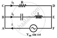
Consider the LCR circuit shown in figure. Find the net current i and the phase of i. Show that i = v/Z`. Find the impedance Z for this circuit.

Advertisements
उत्तर
In the circuit given above consists of a capacitor (C) and an inductor (L) connected in series and the combination is connected in parallel with a resistance R. Due to this combination, there is an oscillation of electromagnetic energy.
Potential across R = Potential of source
P.D. across R =Vm sin ωt
i2R = Vm sin ωt
`I_2 = (V_m sin ωt)/R` ......(I)
q1 is charge on the capacitor at any time t, then for series combination of C, L applying Kirchhoff's voltage law in loop ABEFA.
VC + VL = Vm sin ωt
`q_1/C + L (di_1)/(dt)` = Vm sin ωt
`q_1/C + L (d^2q_1)/(dt^2)` = Vm sin ωt ......(II)
Let q1 = qm sin(ωt + ϕ) .......(III)
`i_1 = (dq_1)/(dt)` = qm ω cos(ωt + ϕ) .......(IV)
`(d^2q_1)/(dt^2)` = qm ω2 sin(ωt + ϕ) ......(V)
Substitute the values of equations (III) and (V) in equation (II)
`(q_m sin(ωt + ϕ))/C - Lq_m ω^2 sin(ωt + ϕ)` = Vm sin ωt
`q_m sin(ωt + ϕ) [1/C - Lω^2]` = Vm sin ωt
At ϕ = 0,
`q_m sin(ωt + ϕ) [1/C - Lω^2]` = Vm sin ωt
`q_m [1/C - Lω^2] sin ωt` = Vm sin ωt
`q_m [1/C - Lω^2]` = Vm
`q_m = V_m/(ω[1/(Cω - Lω)]` ......(VI)
Applying Kirchhoff's junction rule as junction B, i = i1 + i1 using relation I, IV
i = `(V_m sin ωt)/R + q_m ω cos(ωt + ϕ)`
Now using relation VI for qm and at ϕ = 0
i = `[(V_m sin ωt)/R + (V_m ω cos ωt)/(ω[1/(ωC) - ωL])]`
i = `V_m/R sin ωt + V_m/((1/(ωC) - ωl)) cos ωt`
Let A = `V_m/r -= C cos ϕ` ......(VII)
B = `V_m/(1/(ωC) - ωL) = C cos ϕ` ......(VIII)
i = C cos ϕ sin ωt + C sin ϕ. cos ωt
= C [cos ϕ sin ωt + sin ϕ cos ωt]
i = C sin(ωt + ϕ)
Squaring and adding (VII), (VIII)
A2 + B2 = C2 cos2ϕ + C2 sin2ϕ
= C2[cos2ϕ + sin2ϕ]
A2 + B2 = C2
or C = `sqrt(A^2 + B^2)`
ϕ = `tan^-1 B/A = tan^-1 ((V_m)/(1/(ωC) - ωL))/((V_m)/R)`
∴ `tan phi = R/((1/(ωC) - ωL))`
∵ C2 + A2 = B2 = `(V_m^2)/R^2 + (V_m^2)/((1/(ωC) - ωL)^2)`
C = `[(V_m^2)/R^2 + (V_m^2)/((1/(ωC) - ωL)^2)]^(1/2)`
∵ i = `[(V_m^2)/R^2 + (V_m^2)/((1/(ωC) - ωL)^2)]_2 sin(ωt + ϕ)`
I = `V_m [1/R^2 + 1/((1/(ωC) - ωL)^2)]^(1/2) sin(ωt + ϕ)` ......(IX)
And ϕ = `tan^-1 R/((1/(ωC) - ωL))`
∵ I = `V/R` or i = `V/Z`
For ac i = `V/Z sin(ωt + ϕ)` .......(X)
Comparing (IX) and (X)
So, `1/Z = [1/R^2 + 1/((1/(ωC) - ωL)^2)]^(1/2)`
This is the impedance Z for the circuit.
APPEARS IN
संबंधित प्रश्न
Why does current in a steady state not flow in a capacitor connected across a battery? However momentary current does flow during charging or discharging of the capacitor. Explain.
In a series LCR circuit, obtain the condition under which watt-less current flows in the circuit ?
A series LCR circuit is connected to a source having voltage v = vm sin ωt. Derive the expression for the instantaneous current I and its phase relationship to the applied voltage.
Obtain the condition for resonance to occur. Define ‘power factor’. State the conditions under which it is (i) maximum and (ii) minimum.
An L-R circuit has L = 1.0 H and R = 20 Ω. It is connected across an emf of 2.0 V at t = 0. Find di/dt at (a) t = 100 ms, (b) t = 200 ms and (c) t = 1.0 s.
An LR circuit having a time constant of 50 ms is connected with an ideal battery of emf ε. find the time elapsed before (a) the current reaches half its maximum value, (b) the power dissipated in heat reaches half its maximum value and (c) the magnetic field energy stored in the circuit reaches half its maximum value.
The current in a discharging LR circuit without the battery drops from 2.0 A to 1.0 A in 0.10 s. (a) Find the time constant of the circuit. (b) If the inductance of the circuit 4.0 H, what is its resistance?
The potential difference across the resistor is 160V and that across the inductor is 120V. Find the effective value of the applied voltage. If the effective current in the circuit be 1.0 A, calculate the total impedance of the circuit.
In a series, LCR circuit, obtain an expression for the resonant frequency.
Answer the following question.
What is the phase difference between the voltages across the inductor and the capacitor at resonance in the LCR circuit?
Keeping the source frequency equal to the resonating frequency of the series LCR circuit, if the three elements, L, C and R are arranged in parallel, show that the total current in the parallel LCR circuit is minimum at this frequency. Obtain the current rms value in each branch of the circuit for the elements and source specified for this frequency.
For a series LCR-circuit, the power loss at resonance is ______.
A coil of 40 henry inductance is connected in series with a resistance of 8 ohm and the combination is joined to the terminals of a 2 volt battery. The time constant of the circuit is ______.
In a series LCR circuit the voltage across an inductor, capacitor and resistor are 20 V, 20 V and 40 V respectively. The phase difference between the applied voltage and the current in the circuit is ______.
To reduce the resonant frequency in an LCR series circuit with a generator
Which of the following combinations should be selected for better tuning of an LCR circuit used for communication?
Select the most appropriate option with regard to resonance in a series LCR circuit.
In a series LCR circuit, the inductance L is 10 mH, capacitance C is 1 µF and resistance R is 100Ω. The frequency at which resonance occurs is ______.
A 20Ω resistance, 10 mH inductance coil and 15µF capacitor are joined in series. When a suitable frequency alternating current source is joined to this combination, the circuit resonates. If the resistance is made \[\frac {1}{3}\] rd, the resonant frequency ______.
