Advertisements
Advertisements
प्रश्न
In series LCR circuit, the plot of Imax vs ω is shown in figure. Find the bandwidth and mark in the figure.

Advertisements
उत्तर
We know that bandwidth = (ω2 – ω1).
Where ω1 and ω2 are two frequencies where the current amplitude of LCR circuit becomes `12sqrt(12)` times (i.e., Irms) the value of current is maximum at resonant frequency.
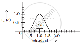
`I = E_0/sqrt(2) = 1/sqrt(2)` = 0.707 Amp
From graph ω1 and ω2 at 0.707A current is 0.8 and 1.2 rad/sec.
So Bandwith ω2.ω1 = 1.2 – 0.8 = 0.4 rad/sec.
APPEARS IN
संबंधित प्रश्न
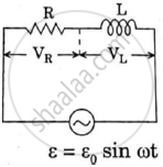
In a series LCR circuit connected to an a.c. source of voltage v = vmsinωt, use phasor diagram to derive an expression for the current in the circuit. Hence, obtain the expression for the power dissipated in the circuit. Show that power dissipated at resonance is maximum
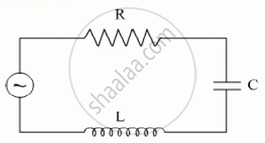
The figure shows a series LCR circuit with L = 10.0 H, C = 40 μF, R = 60 Ω connected to a variable frequency 240 V source, calculate
(i) the angular frequency of the source which drives the circuit at resonance,
(ii) the current at the resonating frequency,
(iii) the rms potential drop across the inductor at resonance.
A series LCR circuit is connected to an ac source. Using the phasor diagram, derive the expression for the impedance of the circuit. Plot a graph to show the variation of current with frequency of the source, explaining the nature of its variation.
Show that in an a.c. circuit containing a pure inductor, the voltage is ahead of current by π/2 in phase ?
Find the value of t/τ for which the current in an LR circuit builds up to (a) 90%, (b) 99% and (c) 99.9% of the steady-state value.
An LR circuit having a time constant of 50 ms is connected with an ideal battery of emf ε. find the time elapsed before (a) the current reaches half its maximum value, (b) the power dissipated in heat reaches half its maximum value and (c) the magnetic field energy stored in the circuit reaches half its maximum value.
The current in a discharging LR circuit without the battery drops from 2.0 A to 1.0 A in 0.10 s. (a) Find the time constant of the circuit. (b) If the inductance of the circuit 4.0 H, what is its resistance?
What will be the potential difference in the circuit when direct current is passed through the circuit?
Answer the following question.
What is the phase difference between the voltages across the inductor and the capacitor at resonance in the LCR circuit?
In an LCR series a.c. circuit, the voltage across each of the components, L, C and R is 50V. The voltage across the LC combination will be ______.
In series LCR circuit, the phase angle between supply voltage and current is ______.
At resonance frequency the impedance in series LCR circuit is ______.
In series LCR AC-circuit, the phase angle between current and voltage is
To reduce the resonant frequency in an LCR series circuit with a generator ______.
Which of the following combinations should be selected for better tuning of an LCR circuit used for communication?
For an LCR circuit driven at frequency ω, the equation reads
`L (di)/(dt) + Ri + q/C = v_i = v_m` sin ωt
- Multiply the equation by i and simplify where possible.
- Interpret each term physically.
- Cast the equation in the form of a conservation of energy statement.
- Integrate the equation over one cycle to find that the phase difference between v and i must be acute.
Define Impedance.
A series LCR circuit containing a resistance of 120 Ω has angular resonance frequency 4 × 10⁵ rad s-1. At resonance the voltage across resistance and inductance are 60 V and 40 V respectively. At what frequency the current in the circuit lags the voltage by 45°. Give answer in ______ × 105 rad s-1.
To an ac power supply of 220 V at 50 Hz, a resistor of 20 Ω, a capacitor of reactance 25 Ω and an inductor of reactance 45 Ω are connected in series. The corresponding current in the circuit and the phase angle between the current and the voltage is respectively:
